
When you're working on ultra-slim signage projects, the 3x6mm profile1 seems perfect. But there's a hidden problem that can destroy your entire installation budget2. Let me share what I've learned after years on the production floor.
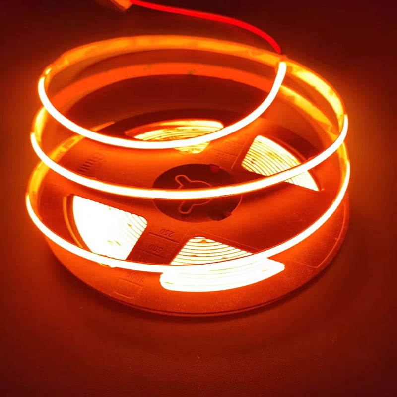
The 3x6mm 2D Bend LED Neon Flex IP653 offers an incredibly slim profile for delicate design work, but its narrow cross-section creates a critical vulnerability: internal circuit stress fractures4 during installation. Understanding PCB flexibility5 and proper handling techniques is essential to avoid costly project failures.

I still remember the first time I saw a contractor nearly cry over a broken installation. The lights worked perfectly in our factory. But on-site, after bending them into tight curves, entire sections went dark. This wasn't a product defect. It was a fundamental challenge with ultra-narrow silicone neon flex that nobody talks about enough.
What Makes 3x6mm 2D Bend Neon Flex So Vulnerable to Damage?
The promise of super slim lighting is attractive. You can create incredibly fine lines and detailed patterns that thicker profiles simply cannot achieve. But this beauty comes with a serious engineering challenge.
The 3x6mm cross-section forces the internal PCB circuit board to be extremely thin and compact. This compressed design leaves almost no room for mechanical flexibility, making the copper traces and solder joints6 highly susceptible to stress fractures when bent or stretched during installation.
Think about what happens during a typical installation. Your installation team receives the neon flex rolled up. They need to fit it into narrow channels, make sharp turns, and sometimes pull it through tight spaces. Each of these actions creates internal stress on the PCB.
The copper traces inside are incredibly thin. When you bend the flex beyond its natural curve radius, microscopic cracks begin to form. Sometimes these cracks are so small that the circuit still conducts electricity during initial testing. But over the next few days or weeks, thermal expansion and contraction widen these cracks until the connection fails completely.
This is what I call "delayed failure syndrome7." The installation looks perfect when you leave the job site. But two weeks later, you get an angry call about dark sections. By then, removing and replacing the damaged sections costs more than the original materials.
I've seen projects where the failure rate reached 15% or higher. That's not just lost product. That's lost labor, lost reputation, and lost profit margins.
Understanding the Root Cause: Material Limitations
The problem starts with how the PCB is manufactured. Most budget suppliers use electrolytic copper8 for their flexible PCB. This type of copper is cheaper to produce but has poor ductility. When you bend it repeatedly or stretch it even slightly, the copper fractures.
Higher quality manufacturers use rolled copper9 instead. Rolled copper has a grain structure that runs along the length of the material, much like wood grain. This structure gives it significantly better flexibility and resistance to bending stress.
But even with rolled copper9, the 3x6mm form factor pushes the limits. The PCB has to be so thin that there's minimal copper thickness to work with. The solder joints6 connecting the LED chips to the PCB are tiny. Any mechanical stress concentrates at these weak points.
The Installation Scenarios That Cause Failures
Let me walk you through the most common failure scenarios I've witnessed:
Scenario 1: Corner Bending When you bend the neon flex around a sharp corner, the outer edge of the PCB stretches while the inner edge compresses. In a 3x6mm profile1, this creates enormous stress concentration. If the bend radius is too tight, the copper trace on the outer edge can snap instantly.
Scenario 2: Pulling Through Channels Many installations require threading the neon flex through aluminum channels or mounting tracks. If the installer pulls too hard, the entire PCB experiences tensile stress. The solder joints6, being the weakest links, can separate from the LED chips.
Scenario 3: Pressure Points When you press the neon flex into a mounting clip or secure it with fasteners, you create localized pressure points10. These points can deform the PCB just enough to crack the copper traces without any visible external damage.
Scenario 4: Temperature Cycling Even if the installation goes perfectly, the neon flex will experience temperature changes during operation. The silicone, PCB, and LED chips all expand and contract at different rates. If there were any microscopic cracks from installation stress, these thermal cycles will widen them until failure occurs.
How Can You Test for Quality Before Large-Scale Installation?
Before you commit to a large order or start a major installation, you need to test the mechanical reliability of your 3x6mm neon flex. Simply turning it on and checking brightness is not enough.
Request sample segments and perform bend-cycle testing11. Bend the sample to the minimum radius you'll use in your project, then straighten it. Repeat this process 20-30 times while monitoring for flickering or dark spots. Additionally, apply gentle tensile stress while the flex is energized to check for connection stability.

Here's my recommended testing protocol:
| Test Type | Method | Pass Criteria |
|---|---|---|
| Static Bend Test | Bend to minimum project radius, hold for 5 minutes while energized | No flickering, no brightness loss |
| Dynamic Bend Test | 30 bend-straighten cycles at minimum radius | Less than 2% brightness variation |
| Tensile Test | Apply 5N pulling force for 30 seconds while energized | No dark sections, no flickering |
| Thermal Cycling | Run at full power for 2 hours, cool for 2 hours, repeat 5 times | Maintain consistent output |
If your sample fails any of these tests, don't proceed with the full order. The failure rate during actual installation will be unacceptably high.
I also recommend asking your supplier specific technical questions. What type of copper do they use in their PCB? What is the copper thickness? What solder paste formulation do they use? A quality manufacturer will have detailed answers. A budget supplier will give vague responses or change the subject.
Pay attention to the solder joints6 under magnification. Quality joints should be smooth and evenly distributed. Poor quality joints look grainy or have incomplete coverage. These poor joints will fail first under mechanical stress.
The Importance of Proper Installation Techniques
Even with high-quality neon flex, improper installation can cause failures. I always provide detailed installation guidelines12 to our clients, but let me share the most critical points here.
Never exceed the minimum bend radius specified by the manufacturer. For 3x6mm profile1s, this is typically around 50-80mm depending on the PCB design. Tighter bends will absolutely cause damage, even if it's not immediately visible.
When threading through channels, use a pulling aid at the front end, not the middle. This distributes the tensile stress more evenly. Never pull from the middle of a long run, as this creates a stress concentration point.
Secure the neon flex every 200-300mm with appropriate mounting clips. This prevents the flex from sagging and creating uneven stress distribution. But don't over-tighten the clips. They should hold the flex in place without compressing it.
Allow for thermal expansion in long runs. If you're installing 5 meters or more in a continuous line, leave small expansion loops every 2-3 meters. This prevents thermal stress from building up and damaging the connections.
What Engineering Solutions Address the Stress Fracture Problem?
After seeing too many failed installations, we made significant changes to our 3x6mm production process. These weren't marketing improvements. These were fundamental engineering modifications to address real-world mechanical stress.
Advanced manufacturers use flexible solder paste13 formulations and reinforced solder joints6 that can absorb mechanical stress without fracturing. Additionally, high-resilience silicone compound14s create a composite structure that distributes stress away from the fragile PCB, significantly reducing installation failures.

Let me explain the technical details of our solution:
Flexible Solder Joint Technology
Standard solder is rigid. When the PCB bends, the solder joint acts as a stress concentrator. We switched to a specialized flexible solder paste13 that contains micro-particles of elastic material. When stress is applied, these particles allow the solder joint to deform slightly rather than crack.
Think of it like the difference between cast iron and spring steel. Both are strong, but only one can absorb impact without breaking.
We also modified our reflow soldering profile to create a specific grain structure in the solder. This grain structure has better ductility while maintaining excellent electrical conductivity. The process requires precise temperature control, which is why many budget manufacturers don't use it.
High-Resilience Silicone Compound
The silicone extrusion process is critical. We developed a proprietary silicone formula with higher elasticity and better adhesion to the PCB. This creates what I call a "composite structure."
When you bend the neon flex, the silicone and PCB move together as a unit. The silicone absorbs much of the mechanical stress before it reaches the fragile copper traces. This is similar to how fiberglass reinforcement works in composite materials.
The key is achieving perfect adhesion between the silicone and PCB during extrusion. If there are air gaps or poor bonding, the protective effect is lost. Our extrusion lines maintain precise temperature and pressure control to ensure consistent bonding across the entire length.
PCB Design Optimization
We also redesigned the PCB layout for 3x6mm profile1s. Instead of straight copper traces, we use a serpentine pattern15 in high-stress areas. This pattern allows the trace to stretch and compress slightly without breaking, similar to how an accordion works.
The LED chip placement is also optimized. By positioning chips away from the maximum stress points during typical bending, we reduce the load on their solder joints6. This requires sophisticated finite element analysis during the design phase, but the reliability improvement is substantial.
Real-World Results: A European Case Study
Numbers and technical details are important, but let me share a concrete example that demonstrates why these engineering improvements matter.
A European signage manufacturer switched to our reinforced 3x6mm neon flex after experiencing a 15% failure rate with their previous supplier. Using our high-resilience solution, they completed a 2000-meter installation with zero field failures, saving thousands in labor costs and protecting their reputation.

This client specializes in high-end retail signage. Their projects involve complex curves, tight radius bends, and demanding aesthetic requirements. When they first contacted me, they were frustrated and desperate.
Their previous installations had been plagued with dark sections appearing weeks after completion. Their installation crews were spending more time on service calls than on new projects. The warranty claims were eating into their profit margins.
We sent them test samples with detailed installation guidelines12. They put our samples through brutal testing—much harsher than my recommended protocol. The samples passed. They placed a trial order for a medium-sized project.
The installation went smoothly. More importantly, three months later, every section was still functioning perfectly. They've now been using our neon flex for over two years with a failure rate below 0.5%. That's not zero, because nothing is perfect in the real world. But it's a dramatic improvement from their previous 15% failure rate.
The financial impact for them was significant. They calculated that the reduced failure rate saved them approximately €12,000 per year in warranty service costs. That's not counting the intangible benefits of improved reputation and customer satisfaction.
This case demonstrates something important: the cheapest product is rarely the most economical choice. Paying slightly more for engineered reliability saves money in the long run.
How Should You Evaluate Suppliers for Critical Projects?
When your project success depends on reliable 3x6mm neon flex, choosing the right supplier becomes crucial. Price should not be your primary consideration. Technical capability and quality consistency matter far more.
Ask potential suppliers for detailed technical specifications including PCB copper type, solder paste composition, and silicone Shore hardness. Request third-party test reports for mechanical stress testing. Most importantly, insist on pre-production samples that you can test under real installation conditions.

Here's my recommended supplier evaluation framework16:
| Evaluation Category | Key Questions | Red Flags |
|---|---|---|
| Technical Transparency | Can they explain their PCB construction? Do they know their copper thickness? | Vague answers, deflecting questions, focusing only on price |
| Quality Documentation | Do they provide test reports? Can they show failure rate data? | No documentation, refusing to provide specs |
| Sample Testing | Will they provide samples for destructive testing? | Only providing "show samples," refusing bend testing |
| Manufacturing Capacity | Do they have dedicated extrusion lines? What's their quality control process? | Outsourcing production, no in-house QC |
| Technical Support | Can they provide installation guidelines12? Do they offer engineering consultation? | Sales-only interaction, no technical staff available |
Be wary of suppliers who only want to talk about price and delivery time. Quality manufacturers want to understand your project requirements first. They ask questions about your installation environment, bend radius requirements, and expected lifespan.
A good supplier will tell you if 3x6mm is actually the wrong choice for your specific application.
Explore the benefits of the 3x6mm profile for signage to enhance your design and installation strategies. ↩
Get tips on managing your installation budget effectively while using LED neon flex. ↩
Learn about the versatility and applications of 2D Bend LED Neon Flex IP65 for your projects. ↩
Discover methods to avoid internal circuit stress fractures and ensure reliable LED installations. ↩
Understand the significance of PCB flexibility in enhancing the durability of LED neon flex. ↩
Learn how to identify quality solder joints to ensure the longevity of your LED neon flex. ↩
Learn about delayed failure syndrome and how to mitigate its impact on your projects. ↩
Explore the limitations of electrolytic copper in PCBs to make informed material choices. ↩
Find out why rolled copper is preferred for flexible PCBs and its advantages over electrolytic copper. ↩
Discover techniques to prevent pressure points that can lead to LED neon flex failures. ↩
Get a step-by-step guide on conducting bend-cycle testing to ensure LED neon flex reliability. ↩
Explore essential installation guidelines to ensure successful LED neon flex projects. ↩
Discover the benefits of flexible solder paste in enhancing PCB durability and performance. ↩
Learn about high-resilience silicone compounds and their importance in LED neon flex applications. ↩
Understand how a serpentine pattern enhances PCB design to reduce stress fractures. ↩
Get insights into creating a supplier evaluation framework to ensure quality in LED product sourcing. ↩