
I've seen it happen too many times. A commercial building owner proudly announces their "LED retrofit project." Six months later, they're calling us back—not because the lights failed, but because something feels wrong. The energy bills dropped, yes, but now there are hot spots, color shifts, and weird performance issues nobody predicted.
Lighting retrofits are not about swapping bulbs. They are about redefining the thermal, electrical, and optical balance of an existing building system. If you only calculate energy savings without recalculating system behavior, you are setting yourself up for invisible failures that compound over time.

Most retrofit failures don't come from bad products. They come from a false assumption: that lower power consumption automatically means better performance. It doesn't. Lower power changes how the entire system operates—and if you don't redesign for that new operating state, you're just moving problems around.
Why Do Most Energy Saving Lighting Projects Fail After Installation?
The industry sells you a simple story. LEDs use less power. They run cooler. They last longer. Install them, save money, done.
But in real commercial building retrofits, this logic breaks down fast. We don't work with isolated light fixtures in controlled labs. We work with complex buildings where every component—power supplies, thermal pathways, structural enclosures—was designed for the old lighting system.

When you drop the power load by 40%, here's what actually happens. Your power supply enters a light-load zone where efficiency drops and output ripple increases. Your thermal management system, designed to dissipate high-wattage metal halide heat, now has to handle a completely different heat distribution pattern. Your ventilation pathways, tuned for one type of convection flow, suddenly operate in a different thermal regime.
The result? Local temperatures rise even though total power consumption falls. This is not a theoretical risk. I have measured it on-site multiple times. One façade project we analyzed showed LED junction temperatures 8–12°C higher than design spec, not because the LEDs were defective, but because the building's thermal structure was still configured for the old light source.
| System Component | Original Design Assumption | Post-Retrofit Reality | Typical Failure Mode |
|---|---|---|---|
| Power Supply | 80–100% load operation | 30–50% load operation | Output voltage drift, ripple increase |
| Thermal Pathway | High-wattage point source heat | Distributed lower-intensity heat | Heat accumulation in unexpected zones |
| Ventilation Design | Convection optimized for 150W+ | Convection ineffective at 40W | Localized thermal stratification |
| Enclosure Sealing | IP rating based on original airflow | Airflow pattern changed | Moisture ingress, condensation |
The critical failure point is this: energy savings change the system's operating boundary conditions, but most retrofits assume the boundary conditions stay the same.
What Happens When You Only Calculate Power Savings Without System Rebalancing?
I want to walk you through a real project failure. This is not hypothetical. A large shopping mall exterior façade retrofit. The initial proposal looked excellent. Replace 300W metal halide with 120W LED strips. Projected energy savings: 40%. IP65 rated. CE certified. Samples tested perfectly.
Four months after installation, complaints started. Some sections of the façade looked dimmer. Others had visible color temperature shifts. Night photos showed discontinuous light bands. When we physically inspected the installation, we found localized yellowing of the silicone extrusion that wasn't present in the first 60 days.

The problem wasn't the LED chips. It wasn't the power supplies individually. It was the system-level mismatch between the new lighting technology and the building's unchanged physical environment.
Here's what we discovered during forensic analysis. The original metal halide fixtures generated intense localized heat, which created strong convection currents that naturally ventilated the façade cavity. The LED replacement generated much less heat, so those convection currents weakened dramatically. Heat that used to escape through convection now accumulated in the sealed enclosure. This raised the ambient temperature around the LEDs by 15–20°C compared to design assumptions.
At the same time, the power supplies were running at 40–50% load, far below their optimal efficiency range. Output voltage stability degraded slightly—not enough to trigger alarms, but enough to shift the LED operating point. Combined with the higher ambient temperature, this pushed the LEDs into a different performance zone than the manufacturer's test data.
Then there was the bin variation issue. The project used LEDs from three different production batches. Under ideal conditions, the bin differences were within tolerance. But when each batch experienced slightly different thermal and electrical conditions—because heat and voltage gradients weren't uniform across the façade—the bin differences became visually noticeable.
None of these issues existed in isolation. They compounded. Higher temperature + voltage drift + bin variation = visible color banding. That's what the client saw six months later.
The lesson: you cannot retrofit lighting without retrofitting the system model.
How Should Professional Engineers Actually Approach Lighting Retrofits?
The correct engineering process starts not with selecting LED products, but with reanalyzing the building's thermal and electrical environment as if you were designing from scratch.
Step one: Recalculate the thermal pathway. You need to answer three questions before you touch a single fixture. Where does heat enter the system now? Where does it exit? Where does it accumulate? If the building's thermal management was designed for high-wattage sources, and you're installing low-wattage sources, the heat distribution pattern will change. You must map this change and redesign the thermal pathway accordingly.
For example, in a typical retail space with recessed ceiling lighting, the original halogen downlights generated enough heat to drive convection through ceiling plenum gaps. When you replace them with LEDs, that convection stops. Now the LED driver heat has nowhere to go. It accumulates inside the fixture housing, raising the LED junction temperature above design limits. The solution isn't better LEDs. The solution is redesigning the enclosure to allow passive cooling under the new thermal conditions.

Step two: Select power supplies based on light-load stability, not just rated capacity. Most retrofit projects select drivers that can handle the full load. That's necessary but not sufficient. You also need drivers that maintain stable output voltage and low ripple when operating at 30–60% capacity. This is not a standard specification. You have to request light-load performance curves from manufacturers and verify them.
| Driver Specification | Standard Approach | System-Optimized Approach |
|---|---|---|
| Load Matching | 100–120% of rated LED power | 150–200% of rated LED power for light-load stability |
| Efficiency Target | >90% at full load | >85% at 30–50% load |
| Output Ripple | <5% at rated load | <3% across 20–80% load range |
| Thermal Derating | Standard datasheet curve | Custom curve validated for actual installation conditions |
Step three: Treat the retrofit as a coupled optical-thermal design problem. You cannot separate the light output from the thermal environment. When you change the light source, you change the heat source. This changes material behavior, surface reflectance, and optical beam patterns. If the ceiling tiles were selected based on their reflectance under halogen lighting, they will perform differently under LED lighting. If the fixture reflectors were shaped to redirect heat away from sensitive components, they may now trap heat because the heat distribution changed.
We worked on a museum retrofit where the original halogen track lights created a specific shadow pattern that the curator considered part of the exhibit design. When we installed direct LED replacements, the shadow pattern changed because the source geometry changed. We had to custom-design optical diffusers to recreate the original shadow effect. This was not a lighting problem. It was a coupled optical-thermal problem that required integrated engineering.
Step four: Understand that visible color differences are system-level symptoms, not component-level defects. When clients report color banding or inconsistent CCT across a large installation, the first instinct is to blame LED binning. But in most retrofit projects, the root cause is systemic. The LEDs may all be within the same bin tolerance, but the system subjects them to different operating conditions—different voltages, different temperatures, different aging rates. These differences accumulate and become visible.
The professional solution is to design the electrical and thermal system to minimize gradients. Use centralized power distribution with regulated voltage to all fixtures. Design thermal pathways to maintain uniform ambient temperature. Select LEDs from single production batches when visual consistency matters. And most importantly, model the system's thermal and electrical behavior before installation, not after complaints arrive.
Step five: Calculate lifecycle performance, not just energy consumption. A retrofit that saves 40% energy but requires maintenance every two years is not better than a retrofit that saves 30% energy but runs maintenance-free for ten years. Many projects focus exclusively on payback period based on energy cost reduction. They ignore the fact that changing the operating conditions changes the aging curve. LEDs that would last 50,000 hours in a controlled environment may last 30,000 hours in a poorly designed retrofit because the thermal and electrical conditions accelerated degradation.
You need to calculate total cost of ownership over the full lifecycle, including maintenance, replacement, and performance degradation. This requires modeling how the system's operating conditions will affect component aging. It's more work than just calculating energy savings, but it's the only way to deliver a retrofit that actually performs better over time.

What Makes a Lighting Retrofit Truly Professional Instead of Just Energy-Efficient?
The difference between a successful retrofit and a problematic one is not the LED efficiency rating. It's whether you treated the project as a system redesign or just a component swap.
When we approach retrofits at Shenzhen Alister Technology Limited, we don't start with product catalogs. We start with site analysis. We measure the existing thermal environment. We map the electrical distribution. We document the optical performance baseline. Only then do we design a lighting system that matches the building's actual physical conditions—not the idealized conditions in a product datasheet.
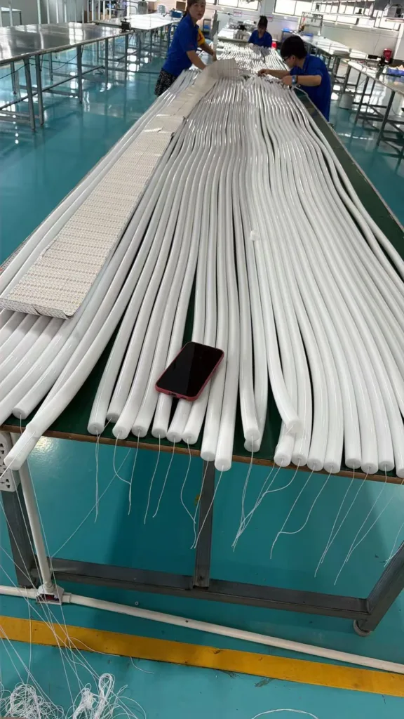
This is why we manufacture silicone neon flex with customizable thermal management features. In a retrofit application, you cannot assume the building will provide adequate cooling. You need lighting products that can manage their own thermal performance across a wide range of ambient conditions. Our food-grade silicone extrusion maintains stable optical performance from -40°C to +60°C not because we over-engineer for extreme conditions, but because commercial buildings operate across that range when you account for seasonal variation, solar loading, and HVAC system behavior.
A truly professional retrofit delivers three outcomes: lower energy consumption, equal or better performance, and stable operation over the design lifetime. If you only achieve the first one, you haven't done a retrofit—you've just postponed problems.
Conclusion
Lighting retrofits fail when engineers treat them as product upgrades instead of system redesigns. Real energy savings come from rebalancing the thermal, electrical, and optical conditions, not just installing more efficient lamps.