
If you've worked on architectural facades, landscape lighting, or chain brand projects, you've probably noticed something frustrating. The LED Silicone Tube system looks perfect during inspection, passes all tests, and everyone celebrates. Then six months later, you get the call. I've been there, and I can tell you: most failures aren't about the LED chip at all.
The real problem with LED Silicone Tube longevity isn't the LED itself—it's the long-term compatibility breakdown between the silicone sleeve, LED strip, adhesives, mounting structure, and environmental stress. Over 80% of field failures trace back to this system-level interaction, not individual component quality.
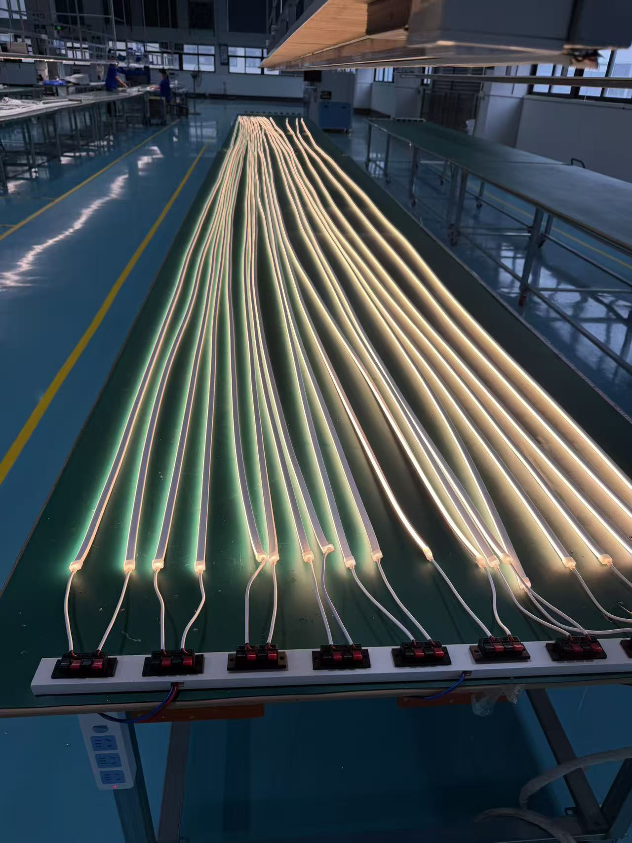
Most people treat the silicone sleeve as a simple protective layer. I used to think the same way. But after investigating dozens of failed installations, I learned the hard truth. The silicone sleeve is the most underestimated yet life-determining component in the entire system. LEDs generate heat, PCBs expand, aluminum channels contract, adhesives age, buildings vibrate, and UV rays continuously attack molecular chains. All these stresses eventually concentrate on the silicone sleeve. You won't see problems during sampling. You won't catch them during acceptance inspection. The real issues typically emerge during the first summer after project delivery.
Why Do LED Silicone Tubes Turn Yellow Within One Year?
I once witnessed a hotel facade project that haunts me to this day. They used transparent LED Silicone Tube paired with high-density LED strips. Every laboratory test passed with flying colors. IP rating? Approved. Tensile testing? Passed. Yellowing resistance? No problem. For three months after installation, performance looked flawless.
Yellowing in LED Silicone Tube isn't caused by poor material quality alone—it results from thermal cycling stress combined with UV exposure. When surface temperatures exceed 75°C daily while experiencing rapid nighttime cooling, molecular chain degradation accelerates exponentially, especially on sun-facing sections.

Then summer arrived. The building curtain wall surface temperature consistently exceeded 75°C. Daily expansion during heat, rapid cooling at night. One complete thermal cycle every 24 hours. Six months in, certain areas showed uneven illumination. One year later, sun-facing sections turned noticeably yellow. Soon after, localized water ingress began. Everyone initially blamed waterproof end cap failure. After disassembly, we discovered something completely different.
The real problem wasn't the waterproofing structure at all. The thermal expansion coefficient mismatch between the silicone sleeve and internal LED strip was too large. Long-term cycling created micro-displacement inside. The LED strip continuously rubbed against the sleeve interior. Solder joints experienced repeated stress. Local encapsulation layers developed fatigue cracks. Moisture then penetrated along these microcracks. Waterproof failure was merely the final symptom. The actual failure origin occurred months earlier. You'll never catch this type of problem in 72-hour testing because it's classic long-term material fatigue failure. It's also the most expensive type of failure in large projects because repair costs far exceed material costs.
| Failure Stage | Visible Symptoms | Actual Root Cause | Detection Difficulty |
|---|---|---|---|
| 0-3 months | None | Micro-displacement begins | Impossible |
| 3-6 months | Slight uneven brightness | Friction wear accumulates | Very difficult |
| 6-12 months | Yellowing appears | Encapsulation cracks form | Moderate |
| 12+ months | Water ingress, complete failure | System breakdown | Easy (too late) |
Can Installation Adhesives Destroy Your LED Silicone Tube System?
Another invisible pit that frequently causes batch returns involves incompatibility between silicone systems and installation auxiliary materials. Many project sites directly use generic market adhesives to fix sleeves for efficiency. Installation day looks fine. Acceptance inspection shows no issues. Three months later, localized debonding starts. Six months later, entire sections fall off.
Generic adhesives used in LED Silicone Tube installations often release migrating small molecules that gradually contaminate the silicone surface. This chemical interaction creates surface tackiness, transparency loss, discoloration, and adhesive strength decay—problems invisible during short-term testing but catastrophic over 6-12 months.
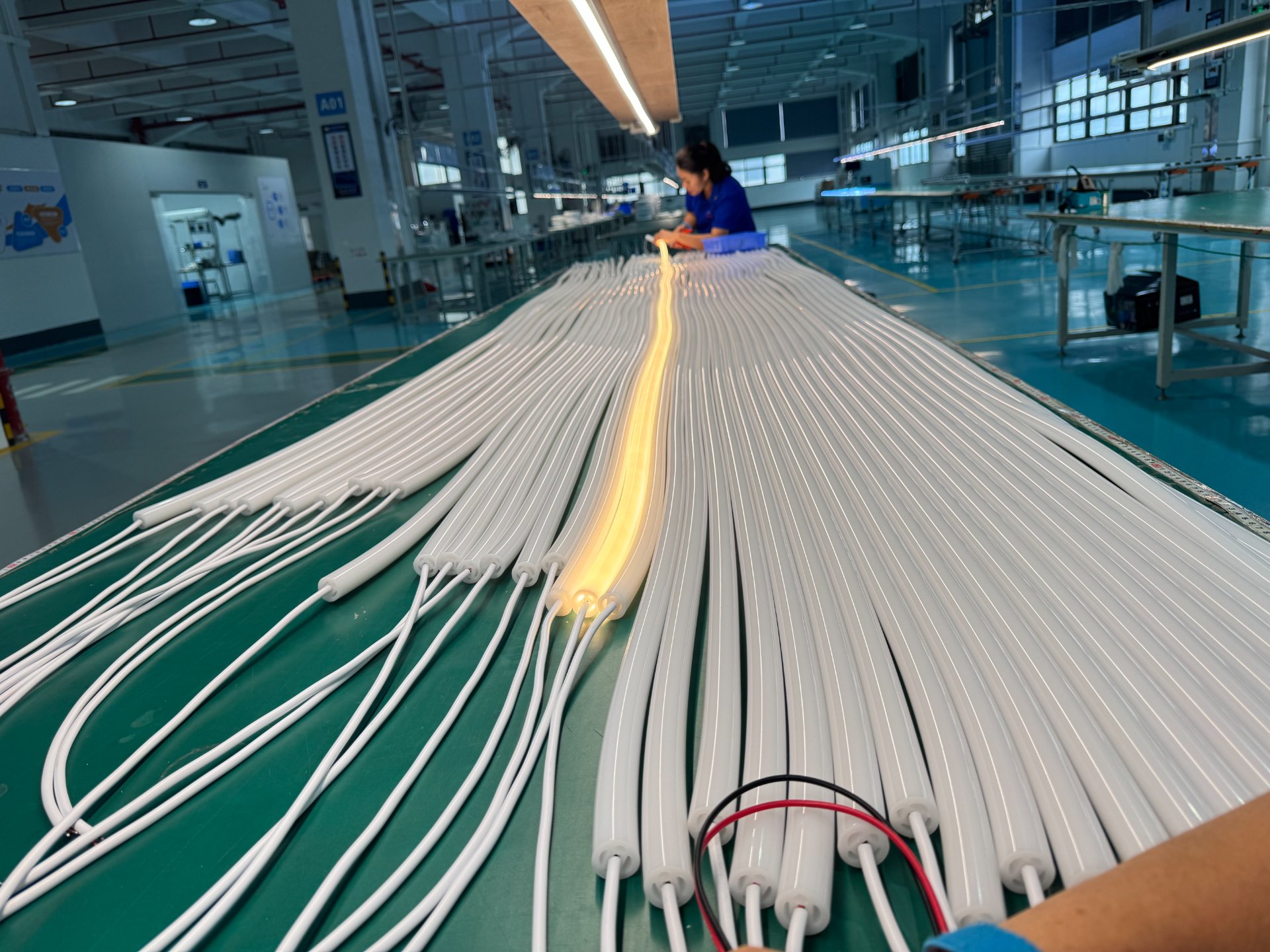
Most people's first reaction blames poor adhesive quality. Actually, the problem typically lies in material system compatibility. Certain adhesives release small molecule substances that continuously migrate to the silicone surface. After long-term action, this causes surface stickiness, decreased transparency, localized discoloration, and adhesive strength attenuation. More serious cases create stress concentration, ultimately forming cracks. Suppliers testing individual materials in isolation will never detect this. Real projects face entire material system interactions. This explains why samples perform normally while mass production fails. Testing environments and real environments aren't remotely the same thing.
I now always request full material compatibility disclosure before projects start. I ask: What adhesives have you tested with this specific silicone formulation? What were the test durations? Did testing include thermal cycling? If they can't answer, I walk away. Because fixing this mistake six months later costs ten times more than preventing it today.
Does Silicone Hardness Really Matter for LED Tube Longevity?
Truly mature projects never treat LED Silicone Tube as an ordinary accessory. We treat it as a structural component exposed long-term to complex environments. First, outdoor projects must control silicone hardness ranges carefully. Too high hardness means poor deformation resistance. After thermal cycling, internal stress concentration easily develops. Too low hardness causes creep deformation over time under gravity influence, especially during continuous long-distance installations.
Optimal LED Silicone Tube hardness for outdoor installations typically ranges between Shore A 60-70. Below this range, gravity-induced sagging occurs during summer heat. Above this range, thermal cycling creates internal stress fractures. Many wave-pattern deformations in illuminated surfaces stem from incorrect hardness design, not installation or LED issues.
Many illuminated surface wave deformations fundamentally result from hardness design errors, not installation problems or LED issues. I've seen installers blamed for "sloppy work" when the real problem was specified material hardness at Shore A 50. Under summer sun, that silicone becomes soft enough to visibly sag between mounting points. No amount of careful installation fixes material specification mistakes.
We also need to pay attention to extrusion process stability. Many projects develop bright lines, dark lines, and light spots not from LED strip problems but from sleeve wall thickness fluctuations causing inconsistent optical diffusion. If during extrusion, wall thickness deviation exceeds tolerance, luminous layer thickness varies, or diffusion material distribution becomes unstable, even using identical LED batches still produces visual color banding. Night scene projects make this especially obvious. Problems amplify further during long-distance observation. What truly needs control isn't simple dimensional tolerance but entire sleeve optical consistency. This requires production monitoring far beyond typical quality control practices.
Why UV Testing Alone Won't Predict LED Silicone Tube Lifespan?
High-UV regions suffer from one severely underestimated problem. Don't just look at yellowing resistance test reports. First examine testing conditions. Many so-called anti-yellowing data only involve hundreds of hours of laboratory UV exposure. Real environments simultaneously present UV radiation, high temperature, rainwater, ozone, acid rain, and salt spray.
Laboratory UV testing for LED Silicone Tube typically simulates only 500-1000 hours of exposure. Real outdoor environments add simultaneous thermal stress, moisture cycling, ozone oxidation, and pollutant deposition. Combined factors accelerate aging rates 3-5 times faster than laboratory predictions, making single-parameter UV tests nearly meaningless for lifespan estimation.
When these factors combine, material aging speed far exceeds laboratory results. Judging LED Silicone Tube lifespan through isolated UV testing provides limited value. We must simultaneously monitor UV aging, thermal aging, temperature-humidity cycling, salt spray corrosion, and long-cycle outdoor exposure. Otherwise, you're just collecting pretty data, not engineering lifespan predictions. I learned this expensive lesson on a coastal boardwalk project where "5-year UV guaranteed" silicone turned brittle and cracked within 18 months. Salt air plus UV plus thermal cycling created synergistic degradation our testing never anticipated.
When evaluating suppliers, I now require accelerated weathering chamber testing that combines all stress factors simultaneously. If they only offer individual parameter testing, their data is academically interesting but operationally useless. Real-world performance requires real-world simulation, even if testing takes longer and costs more.
Where Do LED Silicone Tube Installations Actually Fail First?
For curved installation projects, I pay more attention to minimum bending radius than marketing claims of "bend at any angle." Every failure analysis eventually points to the same pattern. The first damaged location is never the straight section. Failures consistently occur at corner zones, wire exit points, connection areas, and mounting clip edges.
LED Silicone Tube mechanical failures concentrate at stress points: 90° corners, wire penetration zones, connector interfaces, and fixed mounting edges. These locations simultaneously bear mechanical stress and thermal stress. Without proper stress relief design, long-term operation produces solder joint cracks, copper foil breaks, dark illumination zones, and localized light-out failures—problems often misdiagnosed as LED lifespan issues.

These zones simultaneously bear mechanical stress and thermal stress. If structural design doesn't release stress paths, long-term operation produces solder joint cracks, copper foil breaks, dark illumination zones, and localized light-out failures. Many projects assume LED bead lifespan is insufficient. Actually, structural lifespan ended first. I now design installations with deliberate stress relief loops at every corner—slight material excess that allows expansion and contraction without loading solder joints. This simple design change reduced our corner failures by over 90%.
We also specify maximum mounting clip spacing based on sleeve hardness and operating temperature. Tighter spacing seems safer but actually creates more stress concentration points. Wider spacing allows thermal movement but risks sagging. Finding the optimal balance requires calculation, not guessing. Our current standard: 150mm spacing for Shore A 65 hardness at anticipated 60°C maximum surface temperature. Adjust proportionally for different parameters. Installers sometimes complain this is "too complicated." My response: "So is explaining to the client why their $50,000 facade needs complete replacement."
Conclusion
Truly professional LED Silicone Tube solutions never debate whether lights turn on today. We discuss system state after five years of operation. Your concern shouldn't be showroom sample parameters but material system compatibility, extrusion process stability, thermal stress relief design, real-world UV aging validation, and installation structure accommodation for long-term deformation. Project profitability isn't determined by first acceptance inspection but whether you're climbing that building again with a repair crew three years later.