

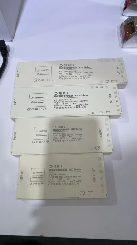
The real question is not "Is my power supply strong enough?" The question is: Did you calculate the true load relationship between your power supply and your LED system from day one?
Most projects fail because they design for specifications that only exist on the test bench. After three months in real environments, those numbers no longer apply. Your system is now running at 110-130% of what you thought was safe.
[Image: LED power supply connected to silicone neon flex installation] 
This is not a power supply problem. This is a system degradation problem. Let me show you what actually happens in the field.
Why Does Your "Safe" Power Supply Calculation Go Wrong After a Few Months?
Most engineers use the same formula for power supply sizing: Total wattage ÷ 80% reserve = Power supply rating.
This formula is correct on paper. But it ignores one critical fact: LED silicone neon flex is not a static load. It is a time-dependent, non-linear thermal-electrical-material system.
[Image: LED neon flex showing thermal degradation patterns]
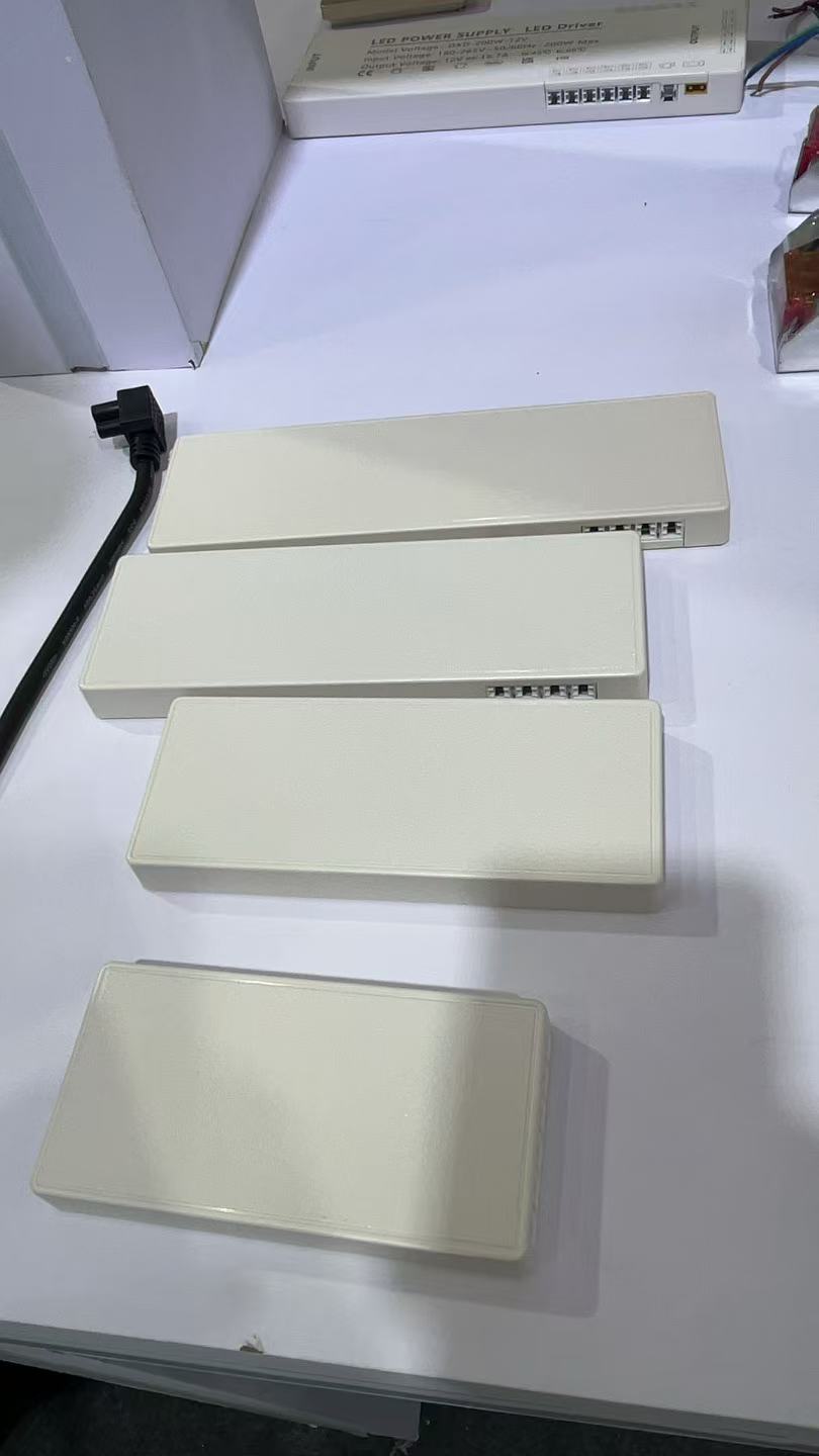
Here is what changes over time in your actual system:
Silicone thermal conductivity degrades under repeated heating and cooling cycles. The material does not transfer heat the same way after six months of operation. Your LED junction temperatures rise. Your forward voltage drops. Your current increases.
Copper foil resistance drifts under bending stress. We have measured resistance increases of 12-18% at bend points after prolonged mechanical cycling. This means your voltage drop is no longer what you designed for.
The interface between silicone and potting compound experiences micro-slip. This creates thermal barriers that were not present during your initial test. Heat builds up. Current compensates. Load increases.
IP-rated enclosures experience micro-pressure changes during thermal expansion. This affects heat dissipation and can create localized hot spots that shift current distribution across the system.
LED bin drift occurs as junction temperature rises. Forward voltage changes. Current demand shifts. Your initial power calculation is now obsolete.
UV exposure reduces light transmission efficiency over time. To maintain the same lumen output, the system automatically draws more current. Your "safe" 20% margin is now gone.
This is why power supplies do not fail in testing. They fail in real buildings, under real environmental stress, after the warranty period starts.
What Actually Happens When "Everything Was Designed Correctly" But the System Still Fails?
I worked on a commercial facade project where everything looked perfect during commissioning. The system was a standard 24V setup. Power supply was rated at 80% of maximum load. Samples passed 72-hour burn-in tests. Light output, color temperature, and brightness all met specifications.
Three months later, the facade started showing localized dimming. Not uniform dimming—just certain sections turning gray instead of going dark. Corner areas developed faint dark bands. During summer heat, some circuits began flickering intermittently.
[Image: LED neon flex facade showing uneven degradation]
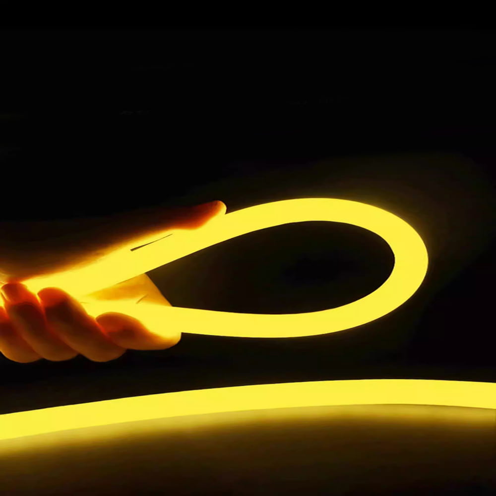
The client replaced the power supplies. No change. They replaced drivers. No change. After six months, the problem escalated to batch-level voltage drop anomalies at cable terminations.
We dismantled failed sections and found the real issue:
Silicone had shrunk slightly under long-term UV and thermal cycling. The copper foil had increased in resistance by 12-18% at bend points. The interface between potting compound and silicone showed micro-delamination. The IP structure had no allowance for thermal expansion displacement. The actual working current was 15% higher than the design value.
The power supply was fine. The system was in chronic overload. And this type of failure never shows up in laboratory testing. It only happens in real buildings, under real environmental conditions, over extended periods.
How Do You Actually Design a System That Will Not Degrade Into Failure?
If you are still using "leave some power margin" as your design philosophy, you are doing static design. Professional engineering requires three things.
You Must Design for Thermal State, Not Cold Nameplate Power
LED strips operating inside architectural structures run 15-35°C hotter than your measurement tools indicate. This directly causes forward voltage to drop, current to increase, driver efficiency to degrade, and long-term power supply loading to drift.
Your power supply design must be based on stabilized thermal-state power, not nameplate power. Otherwise, your margin is a fiction.
[Image: Thermal imaging of LED neon flex in operation]
Here is the calculation method I use in every project:
| Parameter | Cold State | Thermal State | Delta |
|---|---|---|---|
| Forward Voltage (V) | 24.0 | 23.2 | -3.3% |
| LED Junction Temp (°C) | 45 | 68 | +51% |
| Actual Current (A) | 2.5 | 2.7 | +8% |
| True Load (W) | 60 | 62.6 | +4.3% |
Most engineers design for 60W. The real system runs at 62.6W after thermal stabilization. Over time, material degradation pushes this to 66-70W. Your "20% margin" is now 5%.
You Must Treat Material Creep as an Electrical Parameter
People focus on power supplies and forget that material behavior directly changes electrical performance.
Silicone hardness changes over time. This redistributes stress across the structure. Copper foil fatigues under repeated bending. Resistance increases at stress points. Potting compound ages. Thermal resistance rises. These changes are not cosmetic. They alter current pathways and voltage distribution.
Professional engineering is not just power supply selection. It is three-layer integrated long-term drift modeling: material + structure + electrical supply.
[Image: Material stress analysis diagram]
I build a degradation model for every major project. It tracks:
| Time Period | Silicone Hardness Change | Copper Resistance Drift | Thermal Conductivity Loss | Current Increase |
|---|---|---|---|---|
| 0-6 months | -2% | +5% | -3% | +2% |
| 6-18 months | -5% | +12% | -8% | +6% |
| 18-36 months | -8% | +18% | -15% | +10% |
If your power supply does not account for this drift, your system will fail. Not because the power supply is weak. Because the system load has migrated out of the safe zone.
Power Supply Margin Is Not "Bigger Is Better"—It Must Match the System's Mismatch Tolerance Window
Many projects make the mistake of oversizing power supplies. Initial performance is stable. But the system runs in light-load mode. This decreases efficiency and increases voltage ripple. These fluctuations accelerate driver-side instability.
The correct approach is to keep the power supply operating in its stable efficiency range, not in extreme reserve mode.
[Image: Power supply efficiency curve diagram] 
I design systems to operate at 65-75% of power supply capacity. This is the sweet spot where:
Efficiency stays above 90%. Voltage regulation is tightest. Thermal management is optimal. Long-term reliability is highest.
Going above 85% leaves no room for degradation. Going below 50% introduces ripple and efficiency loss. Both accelerate failure.
Conclusion
Power supply sizing is not a selection problem. It is a system-level control problem. You are not just powering lights. You are managing a material-electrical coupled system that changes over time.
Professional engineering means designing systems where current does not drift, heat does not spiral out of control, materials do not degrade past critical points, and structure does not transfer stress into the electrical layer. Projects that achieve this never require rework.