

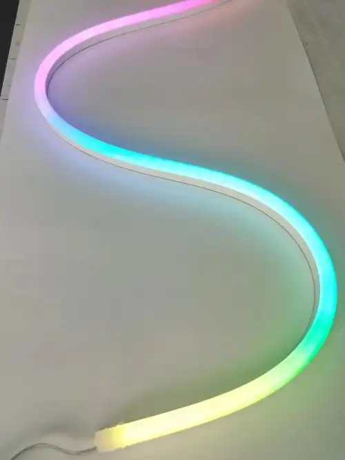
Many businesses choose LED strip lights that look perfect in catalogs. But six months later, they face uneven brightness, color shifts, or complete failures. I have seen this pattern repeat across dozens of commercial projects. The real question is not which strip light performs best today. The question is which system remains stable after three years of continuous environmental stress.
The best LED strip lights for business use are not defined by initial brightness or IP ratings. They are defined by long-term material stability, structural resilience under thermal cycles, and consistent electrical performance across different batches. A true commercial-grade system must account for UV degradation, thermal expansion, copper trace drift, and silicone aging — not just pass factory tests.
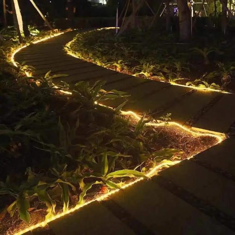
Most purchasing decisions focus on specifications like lumens per watt or waterproof ratings. But specifications describe products at the moment they leave the factory. Real installations operate in continuously changing conditions. Temperature swings between -40°C and +60°C. UV radiation that breaks molecular bonds. Thermal expansion that stresses copper traces. This gap between static specs and dynamic reality is where most projects fail.
Why Do LED Strip Lights Fail After Installation But Not During Testing?
I have reviewed failure reports from building facades, retail chains, and hospitality projects. A clear pattern emerges. Sample batches pass all tests. Early installations work perfectly. Then, after the first seasonal cycle, problems begin. Some areas develop a slight fog. Corner sections dim gradually. Different zones show visible color bands.
LED strip failures in commercial installations are rarely caused by immediate defects. They result from gradual material degradation under real environmental conditions. Silicone molecules break down under UV exposure. Copper traces experience resistance drift from repeated bending. Encapsulation layers separate from silicone extrusions. These processes take months to become visible but start from day one.

The core issue is that businesses select LED strips as static products. But once installed, they become dynamic material systems. Every component interacts with environmental stress. Silicone expands and contracts with temperature changes. Copper oxidizes gradually under moisture. LED chips shift voltage as they age. Power supplies drift in output stability. Installation structures apply continuous mechanical stress.
A typical commercial facade project illustrates this progression. During the first three months, everything appears normal. The first signs emerge during the first hot season. Some sections show reduced brightness without dead LEDs. Different batches reveal slight color differences. The second year brings structural issues. End-section voltage drops more than calculations predicted. Waterproofing develops micro-cracks. Visual consistency breaks down across the entire installation.
When I trace these failures to their root causes, the problems almost never originate from a single bad component. Instead, they come from system-level design errors. Material batches lack consistency in silicone shrinkage rates. Copper foil thickness varies between supply runs. UV aging tests cover 72 hours instead of full seasonal cycles. Installation brackets allow no room for thermal expansion. Adhesive layers migrate into silicone over time. Power supplies operate outside their stable efficiency zones.
This is not product failure. This is system design that ignores time as a variable.
How Do You Control Material Degradation in Outdoor LED Strip Systems?
Many buyers believe IP67 or IP68 ratings guarantee long-term outdoor performance. This assumption causes more project failures than any other factor. IP ratings measure short-term water intrusion resistance. They say nothing about UV degradation speed, thermal cycle recovery, permanent compression set, or surface chalking after prolonged exposure.
For outdoor commercial installations, IP ratings represent minimum protection thresholds, not longevity guarantees. True durability depends on silicone molecular stability under UV radiation, material recovery after thermal cycles, resistance to permanent deformation, and transparency retention over years. Engineering-grade selection requires testing beyond standard IP protocols.

I have tested multiple silicone formulations in accelerated aging chambers. Standard grades show molecular chain breakage after 500 hours of UV exposure at 1.0 W/m². Food-grade, high-molecular silicone maintains structural integrity beyond 3000 hours. The difference appears minor in laboratory conditions. But over three years of real installation, this translates to visible surface cracking versus maintained flexibility.
Thermal cycle performance reveals even sharper contrasts. Standard silicone extrusions show permanent deformation after 200 cycles between -40°C and +60°C. High-grade formulations maintain shape memory beyond 1000 cycles. In practical terms, this means some strips develop waves and sags after one winter. Others remain geometrically stable for five years.
Surface transparency degradation directly affects perceived brightness. Low-grade silicone develops surface haze that reduces light transmission by 15-20% after two years of outdoor exposure. This happens even when LEDs maintain full output. Viewers perceive the installation as "getting dimmer" when the actual problem is material opacity.
The critical specification is not IP rating alone. It is the complete material system. Does the silicone use UV stabilizers or UV blockers? What is the crosslink density after curing? How does shore hardness change across temperature ranges? What is the moisture vapor transmission rate? These parameters determine whether an installation maintains visual quality or gradually degrades into an eyesore.
Why Do Bending Points Become the Weakest Links in LED Strip Installations?
Corner installations consistently show the highest failure rates in commercial projects. Designers often attribute this to installation errors. But the real cause lies in how mechanical stress interacts with electrical and optical performance. Bending a flexible LED strip creates three simultaneous problems that compound over time.
Bending stress in LED strip installations causes copper trace elongation, LED chip mechanical stress concentration, and silicone outer layer compression. These effects increase electrical resistance, create localized dark zones, and initiate micro-crack propagation. Engineering-grade corner solutions require stress-relieved copper design, independent structural support at bend points, and minimum radius enforcement based on long-term values, not initial flexibility.
When you bend a copper trace, you stretch it. Stretching copper increases its electrical resistance. A 90-degree bend in a 12mm wide strip can increase local resistance by 8-12%. This seems minor initially. But resistance creates heat. Heat accelerates LED degradation. After months of operation, bend points run 5-8°C hotter than straight sections. This temperature difference gradually shifts LED forward voltage, creating visible brightness variations.
LED chips themselves experience mechanical stress at bend points. The bond wires connecting chips to traces undergo micro-flexing with every thermal cycle. Over hundreds of cycles, this can cause bond wire fatigue or chip-to-board delamination. The failure mode is subtle. LEDs don't die completely. They just dim by 20-30%, creating dark spots at every corner.
Silicone behavior at bends adds another failure mechanism. The outer surface of a bend goes into tension. The inner surface experiences compression. Repeated thermal expansion and contraction cycles cause these stress patterns to accumulate. After enough cycles, the outer surface develops micro-cracks. These cracks are invisible to casual inspection. But they provide pathways for moisture intrusion, even in IP68-rated products.
I have seen projects where every corner section failed within 18 months while straight runs performed perfectly for five years. The root cause was not defective products. It was installation that forced strips into radii tighter than their long-term mechanical limits. Manufacturers specify minimum bend radius based on immediate mechanical failure. Engineering minimum radius should be 50-100% larger to account for long-term stress accumulation.
Proper corner design requires structural independence. Instead of forcing continuous strips around corners, use dedicated corner connectors with pre-formed angles. This eliminates bending stress entirely. For curved surfaces, use gradual radius transitions over multiple support points rather than sharp bends at single locations. These approaches cost slightly more in materials but prevent the majority of field failures.
How Do Color Temperature Inconsistencies Develop Across Large LED Strip Installations?
A retail chain contacted me after noticing color bands developing across their store facades. Each location used identical LED strip specifications. Installation followed manufacturer guidelines. Yet after six months, some sections appeared warmer while others looked cooler. The visual inconsistency damaged brand perception. Customers complained about "cheap looking" installations.
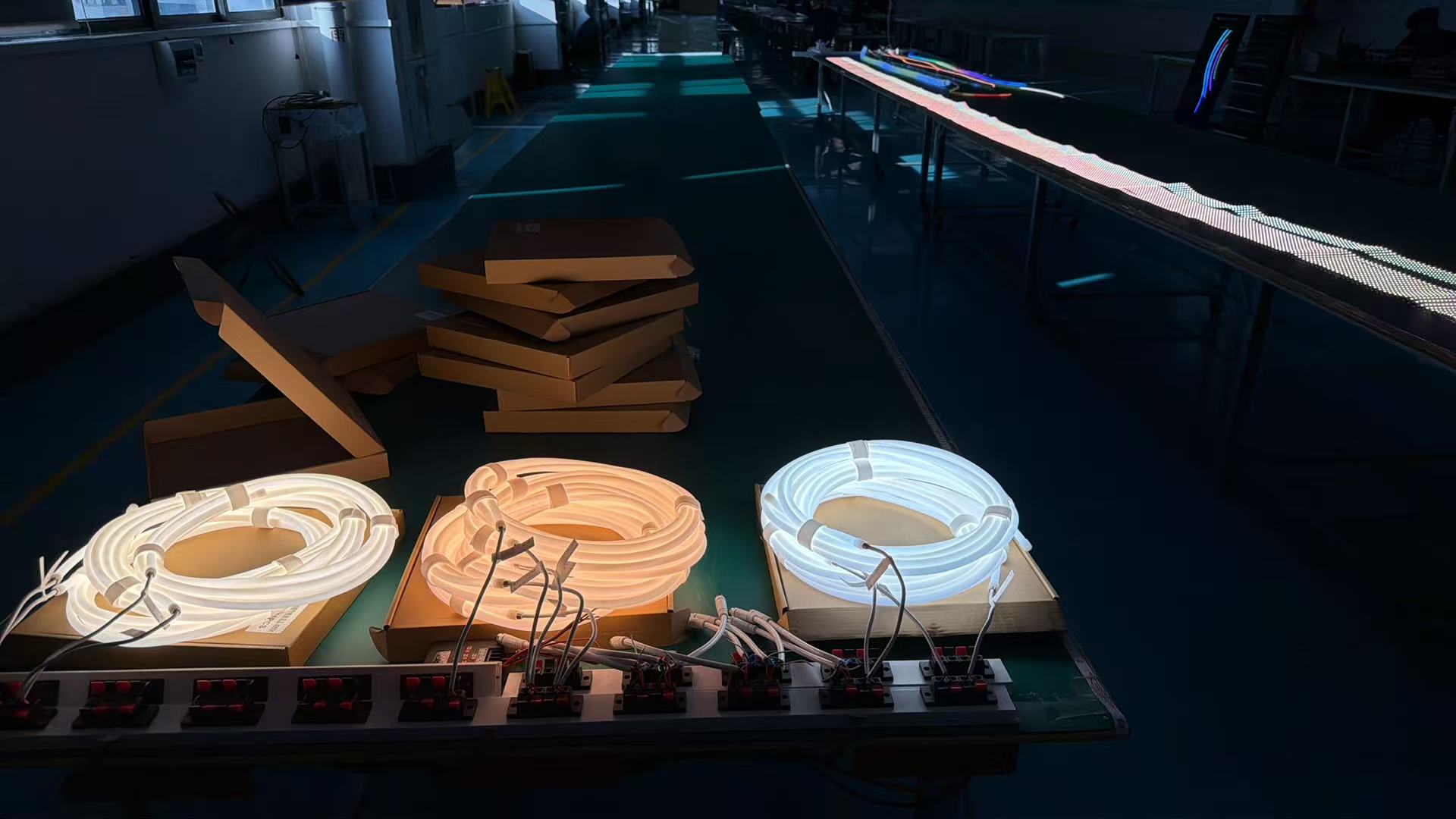
Color temperature inconsistencies in commercial LED strip projects originate from batch-to-batch variations in LED binning, not installation errors. Even chips from the same production run can vary by ±150K in CCT. When different batches mix within a visible installation, these variations create perceptible color bands. Engineering-grade specification requires CCT bin locking, single-batch allocation per visual zone, and commercial-grade color tolerance limits, not consumer-grade ranges.
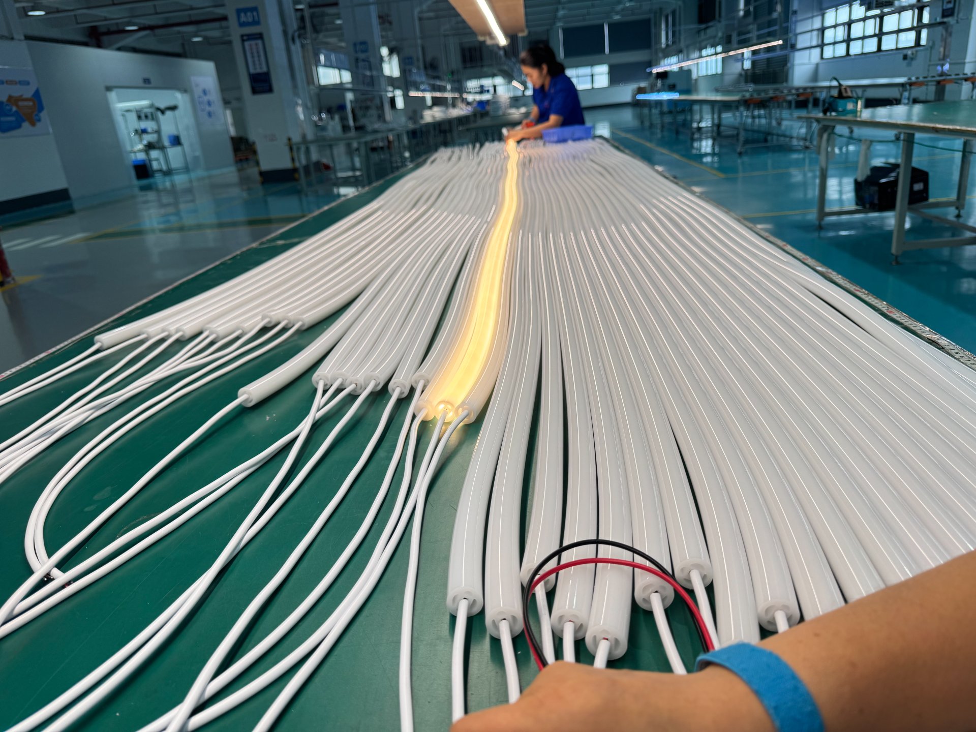
LED manufacturers sort chips into bins based on color temperature, brightness, and forward voltage. A "3000K" bin typically covers 2870K to 3220K. That 350K range is perceptible to the human eye when two sections appear side by side. Standard consumer products accept this variation as normal. Commercial installations cannot.
The problem multiplies when projects source strips across multiple production runs. Each run uses different LED wafer lots. Even with identical target specifications, bin distributions shift. Batch A might center at 2950K. Batch B centers at 3150K. Both meet "3000K" specification. But when installed adjacent to each other, they create visible color breaks.
I tested this systematically using spectroradiometer measurements across a building facade. Sections from the same production batch showed maximum CCT variation of 80K. Sections combining three different batches varied up to 280K. Under daylight, this difference was subtle. Under evening lighting, it became obvious. The building appeared to have distinct temperature zones rather than uniform illumination.
The solution requires supply chain control, not just product selection. For large projects, I specify CCT tolerance of ±50K maximum, not ±150K. I require manufacturers to reserve sufficient inventory from a single production batch to complete an entire visual zone. If a project requires 5000 meters of strip lighting, that full quantity must come from matched batches, not accumulated over time from different production runs.
Some manufacturers resist this requirement. They argue it increases inventory costs and complicates logistics. But the alternative is field failures that cannot be corrected without complete replacement. I have never seen a commercial client accept "within specification" color variation when it creates visible quality problems. Prevention through batch control is always cheaper than remediation through replacement.
For very large projects spanning months of installation, the specification must include color tracking over time. LED phosphors can shift slightly during the first 500 hours of operation. This shift is typically 20-30K and stabilizes afterward. But if early installations age while later additions remain new, a color delta develops. Controlled burn-in before installation, or time-offset planning, prevents this issue.
What Makes a Power Supply System Stable Over Years, Not Just Sufficient in Capacity?
Most LED strip specifications focus on power per meter and total load capacity. A typical calculation looks like this: strips consume 12W/m, installation is 100m, total load is 1200W, so use a 1500W power supply with 25% overhead. This approach meets immediate electrical requirements. But it ignores long-term stability factors that determine whether the system maintains consistent performance.
Power supply selection for commercial LED strips must optimize for long-term efficiency zones, not just capacity margins. Supplies operating continuously at 40-60% load maintain tighter voltage regulation, lower ripple current, and stable thermal profiles compared to units running at 80-90% capacity. Engineering-grade power system design includes voltage drift absorption, thermal load balancing, and efficiency optimization across the expected operational range.
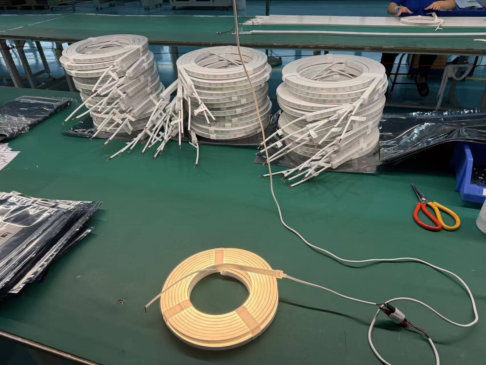
I measured voltage stability in power supplies under different load conditions over 2000-hour test periods. Supplies operating at 85% capacity showed output voltage drift of 0.8-1.2V over this period. Supplies at 50% capacity maintained drift below 0.3V. This difference seems small. But LED strips are constant current devices. Voltage variation causes current variation, which causes brightness variation.
Ripple current reveals an even larger performance gap. Heavy-loaded supplies generate ripple currents that can reach 8-12% of nominal output. This ripple passes directly into LED strips, creating optical flicker. Even when flicker frequency exceeds human perception, it causes eye strain in commercial environments. Lightly loaded supplies maintain ripple below 3%, providing genuinely stable illumination.
Thermal cycling effects compound these problems. A power supply at 90% load runs its components near their thermal limits. Capacitors, MOSFETs, and transformers experience accelerated aging. After 18 months of continuous operation, component drift causes further voltage instability. By 36 months, some supplies develop significant performance degradation. Replacement becomes necessary not because of failure but because of unacceptable drift.
The solution is counterintuitive. Instead of minimizing the number of power supplies to reduce cost, I specify more supplies at lower individual loads. A 100m installation might use four 400W supplies instead of two 800W units. This approach increases equipment cost by perhaps 15%. But it extends system lifetime by 2-3x and maintains visual consistency throughout that period.
Load distribution also matters. LED strips show voltage drop along their length. Longer runs experience greater voltage differential between beginning and end. This creates brightness variation. Engineering-grade designs inject power at multiple points along long runs, maintaining voltage within ±5% across the entire length. Consumer-grade installations inject power only at one end, accepting 10-15% voltage variation.
Current balancing between parallel strings requires active management. When multiple LED strips connect to a single supply, manufacturing variations cause current imbalance. Some strings draw more current than others. This imbalance grows worse as components age at different rates. Active current balancing circuits or separate constant-current drivers per string maintain uniform performance over years.
Conclusion
The best LED strip lights for business are not determined by initial specifications but by engineered long-term stability. Material systems must resist UV degradation, thermal cycles must not cause structural failure, and electrical performance must remain consistent across years. True commercial-grade selection requires understanding that installations are not static products but dynamic systems that either degrade gracefully or fail prematurely based on engineering decisions made during specification. I have learned that preventing field failures costs far less than correcting them after installation.