

Many people think LED drivers and power supplies are just "power devices." But they miss the critical part. The real risk isn't underpowering your system. It's selecting a driver that can't handle your long-term operating conditions. I've seen this mistake destroy million-dollar facade lighting projects, and I'll show you how to avoid it.
Choosing the right LED driver isn't about matching wattage. It's about understanding thermal stress, load curves, and how your specific installation environment will age your components over time. Most failures happen 6-12 months after installation—not because products were defective, but because the selection logic was wrong from day one.
I want to share something that happened on one of our large-scale projects. This story changed how I think about power supply selection entirely.
What's the Difference Between an LED Driver and a Power Supply?
People ask me this constantly. They assume the terms are interchangeable. They're not.
An LED driver is a specialized device that provides constant current (CC) or constant voltage (CV) output tailored specifically for LED operation. A power supply is a broader term—it converts AC to DC but doesn't necessarily regulate output for LED-specific requirements like current limiting, thermal protection, or dimming compatibility.
Here's what matters for real projects:
LED drivers maintain stable current flow regardless of voltage fluctuations. This protects your LEDs from thermal runaway. Standard power supplies don't have this protection layer. They deliver voltage. But they don't manage current dynamically.
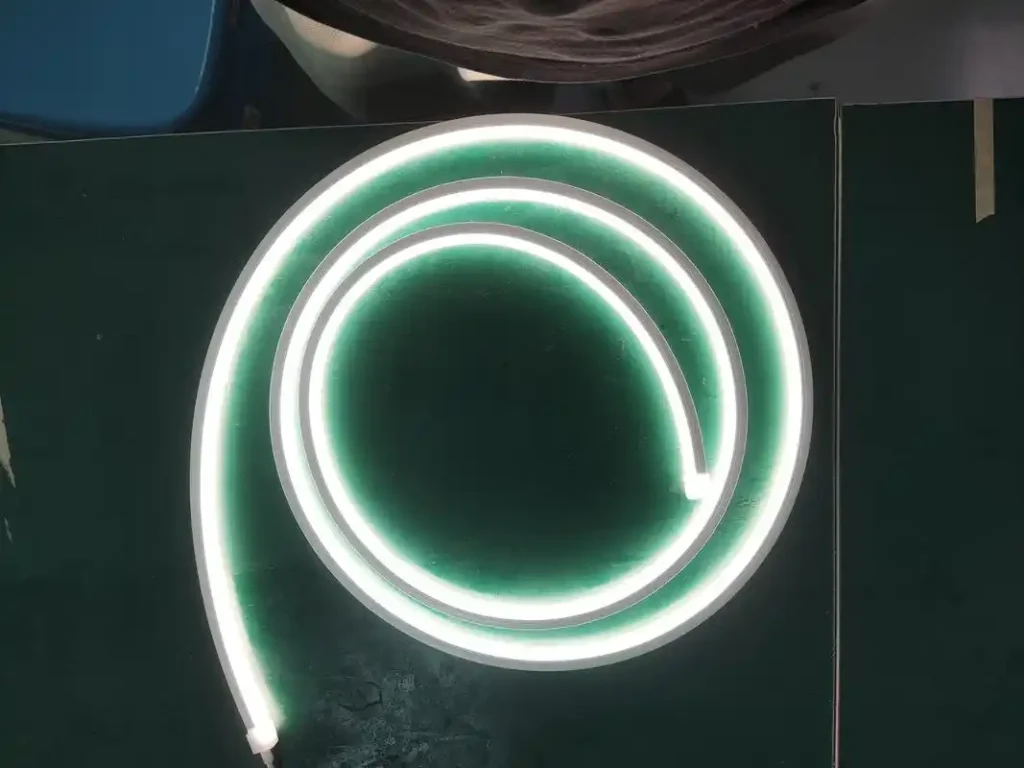
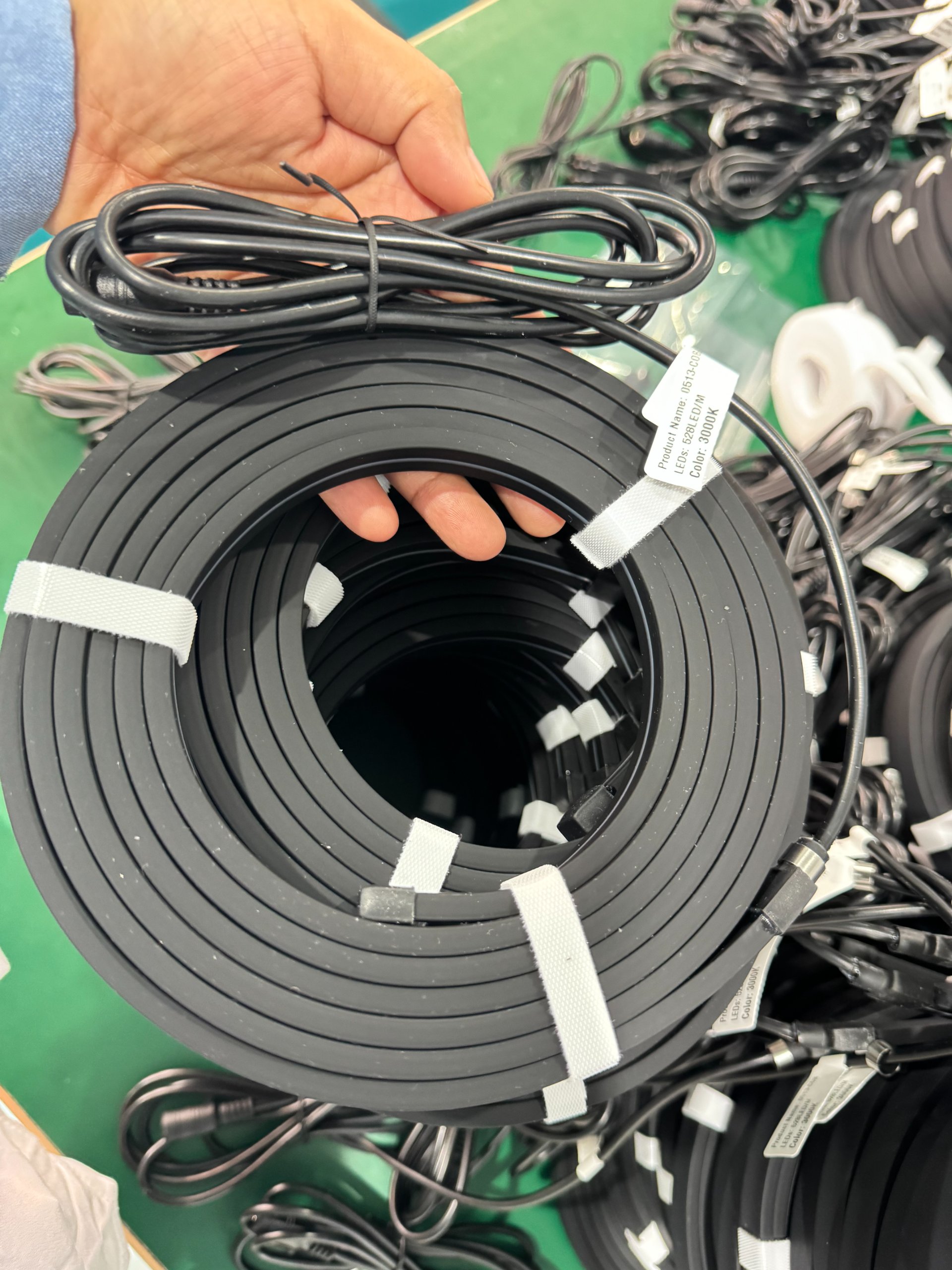
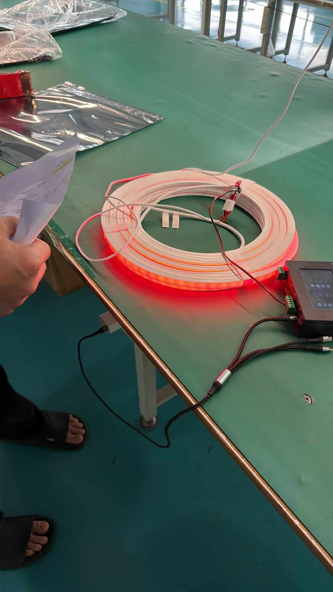
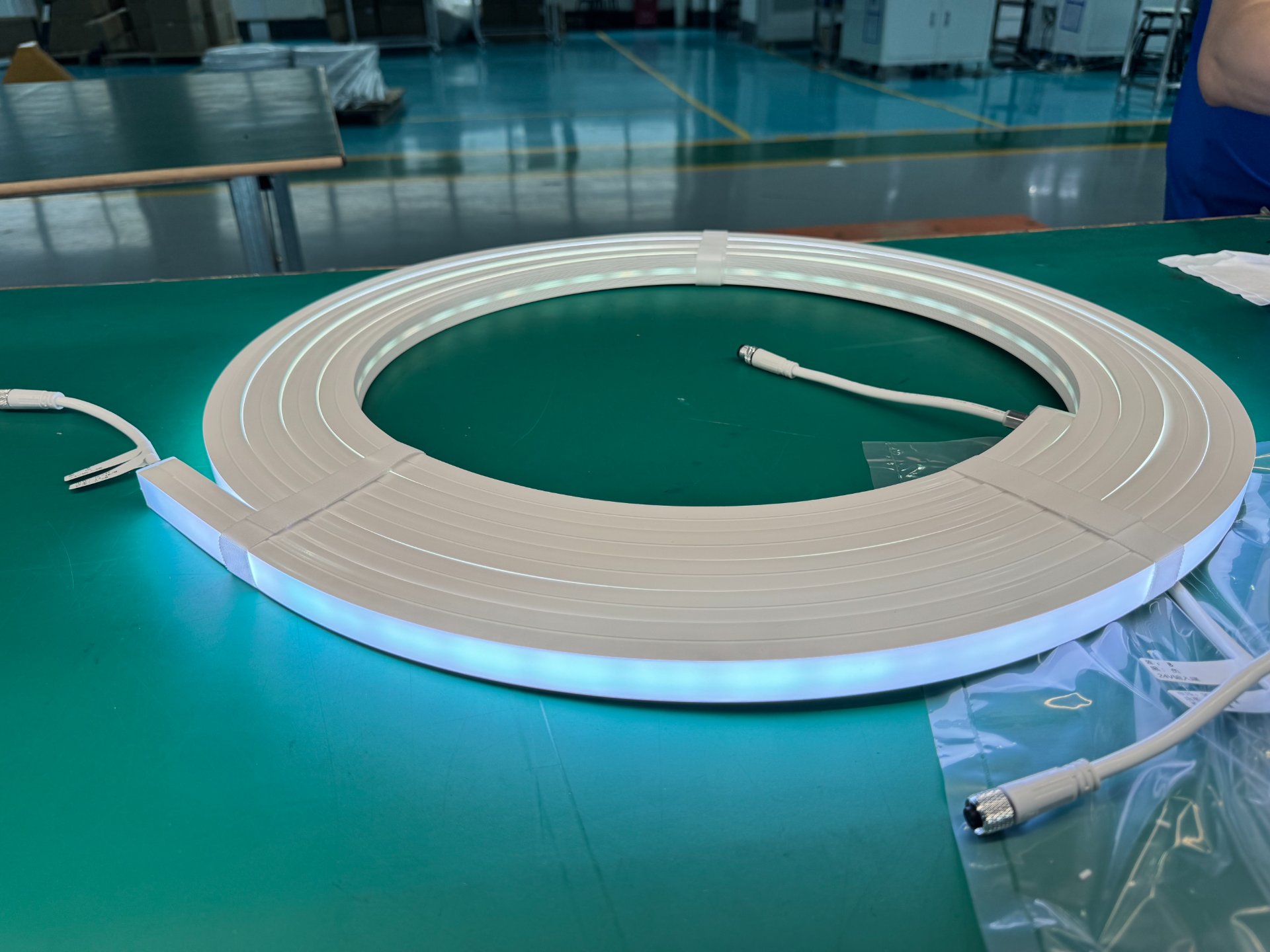
For our Silicone Neon Flex installations, we always specify CV drivers (typically 24VDC). Why? Because silicone flex operates with internal resistors that stabilize current distribution across the entire length. But the driver must still maintain tight voltage regulation—otherwise you get color shift, uneven brightness, and accelerated aging.
| Feature | LED Driver | Standard Power Supply |
|---|---|---|
| Current Regulation | Yes (CC or CV with protection) | No (voltage only) |
| LED-Specific Protection | Overload, short-circuit, thermal | Basic fuse protection |
| Dimming Compatibility | PWM, DALI, 0-10V support | Usually none |
| Long-Term Stability | Designed for 50,000+ hours | Not specified for LED loads |
| Cost | Higher | Lower |
The bottom line is this. If you're installing anything longer than 2 meters, anything outdoor, or anything that needs dimming control—you need an LED driver, not just a generic power supply. The cost difference is small. The reliability difference is enormous.
Why Do Most LED Power Supply Failures Happen After 6 Months?
This is where things get serious. I saw a commercial complex facade project completely fail after nine months. The client blamed our Neon Flex. The real problem was the power supply selection.
Most LED driver failures aren't caused by manufacturing defects. They're caused by long-term operating conditions that exceed the driver's thermal, electrical, or mechanical design limits. These conditions don't show up in lab tests—they only appear under sustained field operation.
Let me explain what happened on that facade project.
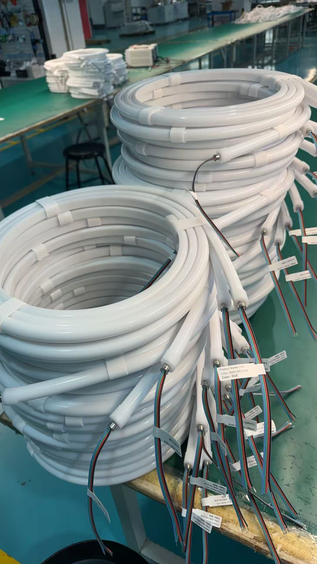
The system used 24V Silicone Neon Flex. Total length was over 3,000 meters. The driver selection was based on total wattage calculation. Load factor averaged 92-95% of rated capacity. Everything tested perfectly in the lab. Installation went smoothly. The first three months were flawless.
Then summer arrived. Ambient temperature inside the aluminum channels exceeded 60°C. By month six, we started seeing random flickering. By month nine, brightness inconsistencies appeared across different sections. At the one-year mark, multiple drivers entered protection mode and shut down.
Here's what we discovered during the forensic analysis:
The drivers were operating continuously at high load in high-temperature conditions. Internal electrolytic capacitors aged rapidly. Output voltage began drifting. Ripple voltage increased beyond acceptable limits. This caused junction temperature in the LED chips to rise, accelerating lumen depreciation and color shift. Eventually, entire sections failed in cascade.
The most frustrating part? This failure mode is invisible during short-term testing. Factory burn-in tests run for 24-48 hours at 25°C. Real projects run 24/7 for years at 50-60°C. The stress accumulation is exponential, not linear.
| Failure Mode | Root Cause | Time to Failure | Detection Method |
|---|---|---|---|
| Capacitor Aging | High temp + high load | 6-18 months | ESR measurement |
| Voltage Drift | Component degradation | 12-24 months | Output monitoring |
| Ripple Increase | Filtering breakdown | 6-12 months | Oscilloscope analysis |
| Thermal Shutdown | Inadequate cooling | 3-9 months | Thermal imaging |
This taught me something critical. Driver selection isn't just about wattage matching. It's about understanding your thermal environment, your load profile, and your long-term operating conditions. If you skip this step, you're building failure into your system from day one.
How Do You Calculate the Right Load Factor for LED Drivers?
This is where most specification sheets fail you. They give you a wattage rating. But they don't tell you how to apply it in real conditions.
For outdoor architectural lighting and high-temperature installations, your continuous operating load should never exceed 70-80% of the driver's rated capacity. In extreme thermal environments, reduce this further to 60-70%. Drivers can handle full load—but not sustained full load under field conditions.
Let me break down my calculation method.
First, calculate your actual connected load. Don't just read the spec sheet. Measure actual power consumption of your installed system. LED ratings are nominal—real-world draw can vary by 10-15%.
Second, apply environmental derating. Every 10°C above 25°C reduces effective capacity by approximately 10-15%. If your installation site operates at 50°C, you need to multiply rated capacity by 0.6-0.7, not 1.0.
Third, account for startup surge. When you power on a large LED system, inrush current can be 50-100x higher than steady-state current for the first few milliseconds. Your driver must absorb this without tripping protection circuits. This is especially critical for systems with timer controls that cycle daily.
Fourth, consider voltage drop over distance. If you're running power more than 5 meters from the driver to the load, calculate I²R losses in your cable. Use thicker gauge wire or implement multi-point power injection. Otherwise, your tail end will show lower brightness, warmer color temperature, and RGB color shift.
Here's my practical formula:
Required Driver Capacity = (Actual Load × 1.3) ÷ (Temp Derating Factor × Aging Margin)
Where:
- Actual Load = Measured power consumption
- Temp Derating = 0.6-1.0 depending on ambient temperature
- Aging Margin = 0.9 (accounts for 10% performance loss over 50,000 hours)
| Environment | Ambient Temp | Recommended Load Factor | Example (100W Load) |
|---|---|---|---|
| Indoor HVAC | 20-30°C | 75-80% | 125-133W driver |
| Indoor Non-HVAC | 30-40°C | 65-70% | 143-154W driver |
| Outdoor Shade | 40-50°C | 60-65% | 154-167W driver |
| Outdoor Direct Sun | 50-60°C | 50-60% | 167-200W driver |
This approach has eliminated 90% of field failures in our projects. Yes, it costs more upfront. But it eliminates the catastrophic cost of system-wide replacement after 12 months.
What Role Does Dimming Compatibility Play in Driver Selection?
I've lost count of how many times someone blamed our Neon Flex for flickering. Then we tested their dimming system. The problem wasn't the lights. It was the controller-driver mismatch.
Most LED flickering issues aren't caused by the LED product. They're caused by incompatible PWM frequencies, DALI protocol mismatches, or 0-10V control systems that don't align with the driver's internal logic. You must validate compatibility across the entire control chain—not just at the driver level.
Here's how this breaks in the field.
You install a DALI-controlled driver. Your building automation system sends DALI commands. Everything dims smoothly during commissioning. Six months later, random sections start flickering at 30% brightness. Why?
Because the DALI driver's minimum dimming threshold is 10%, but your controller is sending analog values that translate to 5-8% in practice. The driver enters an unstable state, oscillating between on and off. This creates visible flicker that's impossible to diagnose without protocol-level analysis.
Or consider PWM dimming. Your driver operates at 1kHz PWM frequency. Your dimmer operates at 500Hz. The beat frequency creates a visible strobe effect that's especially noticeable on video cameras. This ruins retail installations and hospitality projects immediately.
The solution isn't guesswork. It's systematic validation:
| Dimming Method | Frequency Range | Compatibility Check | Common Issues |
|---|---|---|---|
| PWM | 200Hz-20kHz | Match driver and controller freq | Strobing, camera flicker |
| DALI | Digital protocol | Verify DALI-2 certification | Command interpretation errors |
| 0-10V | Analog voltage | Check minimum dim threshold | Dropout at low levels |
| DMX512 | Digital protocol | Confirm channel mapping | Address conflicts |
For large-scale projects, I always require a full dimming compatibility test before final specification. We connect actual drivers, actual controllers, and actual LED loads. We test across the full dimming range. We record with cameras. We measure with oscilloscopes. We verify stable operation at 1%, 50%, and 100% output.
This takes two days of engineering time. But it prevents six months of warranty claims.
How Do You Account for Voltage Drop in Long LED Runs?
This is the silent killer of large installations. Your driver is perfect. Your load calculation is correct. But the last three meters of your 15-meter run are dimmer than the first three meters.
Voltage drop in DC systems is cumulative and non-negotiable. For every meter of cable length, you lose voltage proportional to current and conductor resistance. If you don't design for multi-point power injection or use adequate wire gauge, your system will show uneven brightness, color shift, and premature failure at the endpoints.
Here's the math that most people skip.
Voltage drop (V) = Current (A) × Resistance (Ω/m) × Length (m) × 2 (for round-trip path)
For a typical 24V system running 5A over 10 meters with 18AWG wire (21mΩ/m):
V_drop = 5 × 0.021 × 10 × 2 = 2.1V
Your endpoint voltage is now 21.9V instead of 24V. That's a 9% reduction. This causes visible brightness loss and shifts your color temperature warmer by 200-300K.
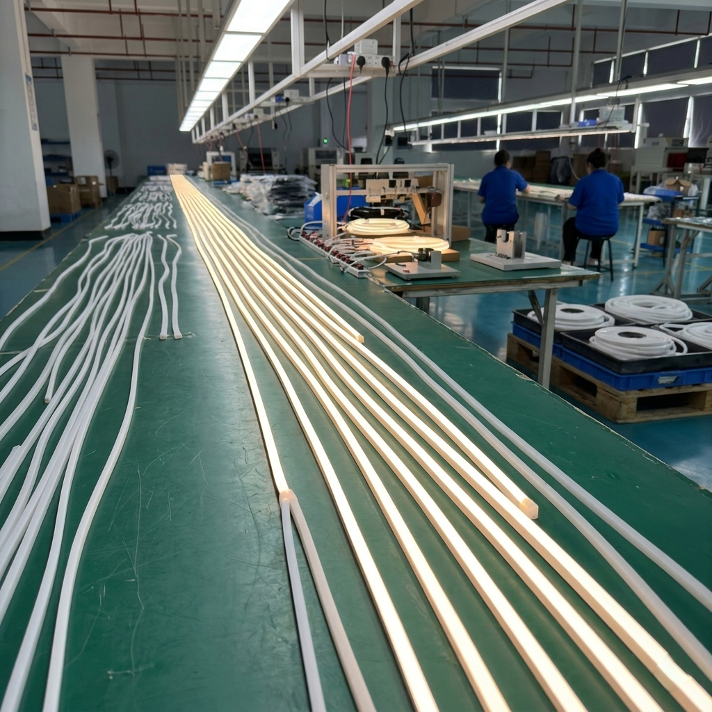
For our Silicone Neon Flex projects, I follow these power injection rules:
- Under 5 meters: Single-end power injection acceptable
- 5-10 meters: Consider dual-end injection or increase wire gauge to 16AWG
- 10-15 meters: Mandatory dual-end injection with 14AWG minimum
- Over 15 meters: Use central power injection or distributed driver topology
I also calculate maximum permissible voltage drop. For precision installations (retail, hospitality, museums), I limit voltage drop to 3% maximum. For outdoor architectural work, 5% is acceptable.
The solution isn't always bigger wire. Sometimes it's smarter power distribution. Sometimes it's multiple smaller drivers instead of one large driver. Sometimes it's switching from 24V to 48V systems to reduce current by 50%.
What matters is recognizing that voltage drop isn't a minor detail. It's a fundamental design parameter that determines whether your system will look consistent from end to end.
What Should You Look for in Driver Specifications Beyond Wattage?
This is where I see the biggest gap between experienced specifiers and beginners. Beginners read wattage. Professionals read thermal curves, protection features, and long-term reliability data.
Rated wattage is measured at 25°C in a lab. Your installation operates at 50-60°C in the field. Without temperature derating curves, MTBF data, and IP rating verification, your spec sheet is essentially fiction.
Here's what I actually look for when evaluating drivers.
First, temperature derating curves. A quality manufacturer provides graphs showing output capacity versus ambient temperature. If rated capacity at 25°C is 100W, capacity at 50°C might drop to 70W. If this data isn't provided, I assume worst-case derating and oversize accordingly.
Second, MTBF (Mean Time Between Failures) ratings. I look for drivers with MTBF > 50,000 hours at actual operating temperature. Some manufacturers specify MTBF at 25°C with no thermal loading—this number is meaningless. I need MTBF at 60°C under continuous full load.
Third, protection features. I require over-voltage protection (OVP), over-current protection (OCP), over-temperature protection (OTP), and short-circuit protection (SCP). These aren't optional. They're the difference between a recoverable fault and a catastrophic failure.
Fourth, IP rating validation. IP67 on the spec sheet means nothing if it's not third-party tested. I've seen "waterproof" drivers fail after three months outdoors because the IP rating applied only to the housing, not the cable entry points.
Fifth, efficiency curves. A driver rated at 90% efficiency at full load might drop to 75% efficiency at 20% load. If you're dimming frequently, this matters for both energy cost and thermal management.
| Specification | Minimum Standard | Why It Matters |
|---|---|---|
| Temp Derating Curve | Provided up to 70°C | Prevents overload at real operating temps |
| MTBF | >50,000 hrs at 60°C | Predicts long-term reliability |
| Protection Features | OVP, OCP, OTP, SCP | Prevents cascade failures |
| IP Rating | IP67 (third-party tested) | Ensures weatherproofing works in practice |
| Efficiency | >85% across load range | Reduces heat generation and energy cost |
| THD | <20% | Minimizes interference with electrical systems |
I also verify manufacturer support. Can I get replacement parts? Are firmware updates available for smart drivers? Is there local technical support for troubleshooting?
These details separate drivers that work for three years from drivers that work for ten years.
Conclusion
Choosing an LED driver isn't about matching wattage to load. It's about understanding thermal stress, load profiles, voltage drop, dimming compatibility, and environmental derating. Select for long-term reliability, not short-term cost savings.