
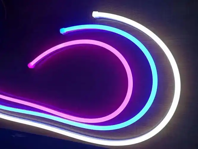
Many people choose Neon Flex 360 LED Lights because they deliver true 360° omnidirectional illumination. But I've learned that the most impressive visual effect can hide the most dangerous structural risks. The real challenge is not making the light bright today—it's ensuring it remains consistent after five years of continuous environmental stress.
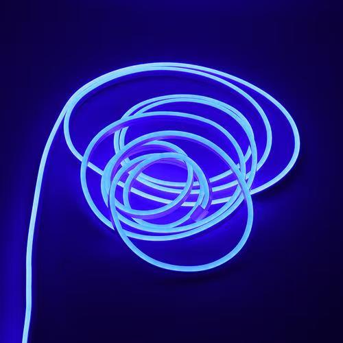
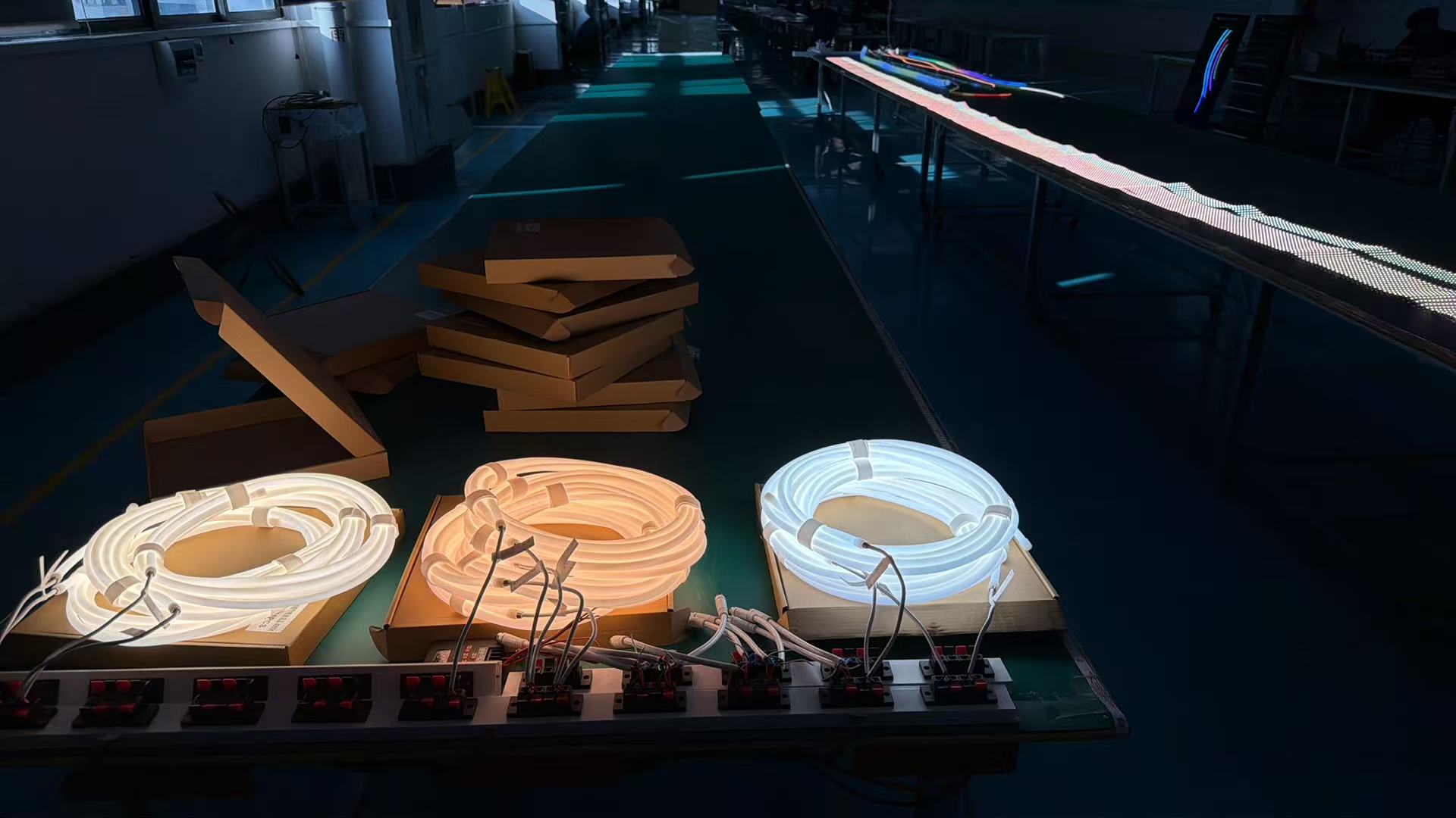
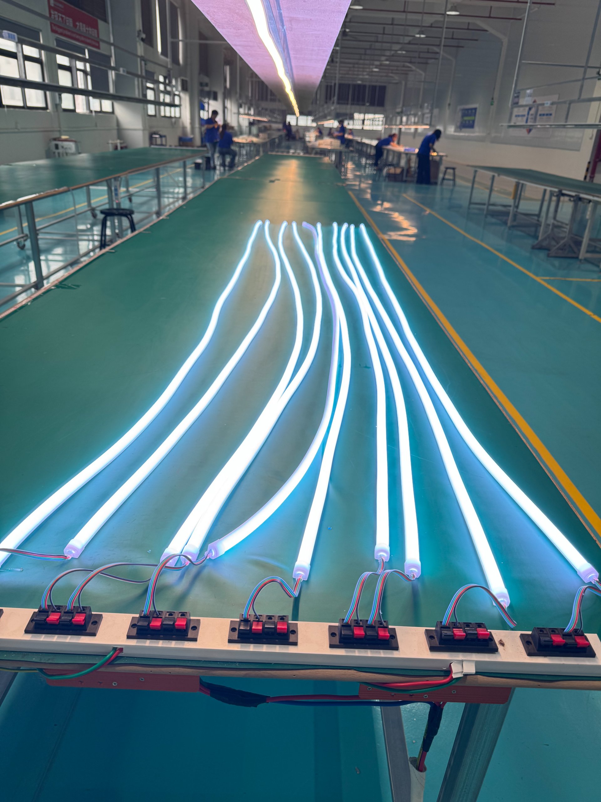
Neon Flex 360 LED lights are specialized silicone-extruded linear lighting systems that emit uniform light in all directions. Unlike traditional single-sided LED strips, these products use a circular cross-section design that allows light to radiate 360 degrees, making them ideal for suspended installations, logo creation, and architectural accent lighting where visibility from multiple angles is critical.
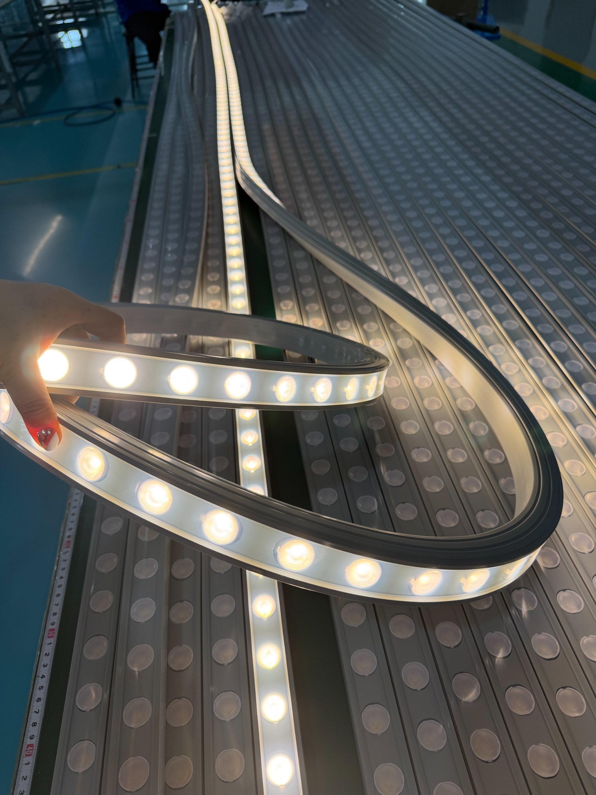
I've worked with dozens of commercial lighting projects over the past several years. The pattern is always the same. Projects look stunning during acceptance inspection. Two years later, clients start calling about yellowing, sagging, uneven brightness, and failed connections. Most people blame the LED chips. I've found that the real culprit is almost always the 360° structure itself, which was never treated as an engineering system.
What Makes 360° Neon Flex Fundamentally Different from Standard LED Strips?
Most lighting professionals think of 360° neon flex as simply "a brighter version" of regular LED strips. This is a dangerous oversimplification. The structural behavior is completely different.
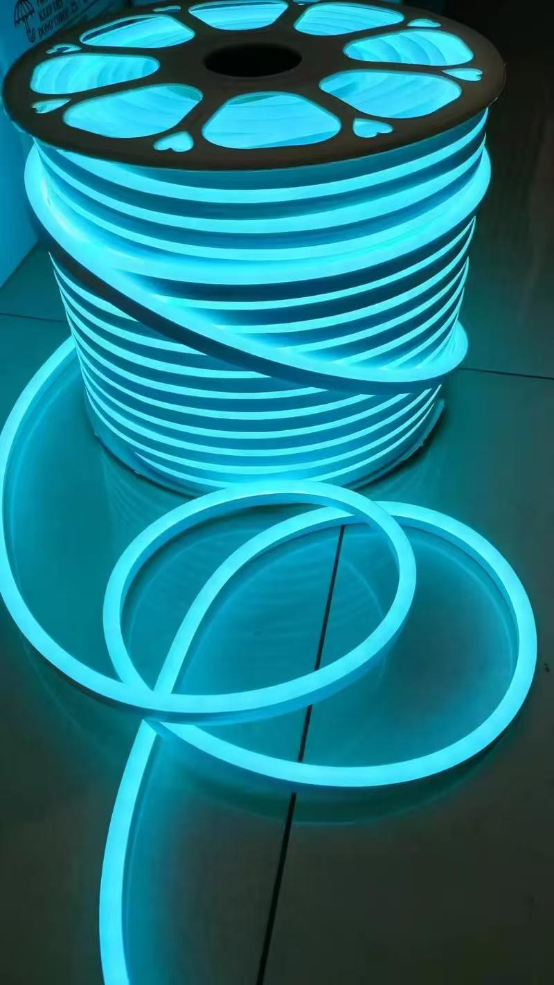
A 360° Neon Flex is not just a light source—it's a flexible cylindrical structure that must withstand omnidirectional UV exposure, thermal accumulation across the entire cross-section, gravitational stress on a circular form, and wind loads that cannot dissipate through a single plane.
Why Traditional Testing Methods Fail for 360° Products
Standard LED strips have one emitting surface. When they age, degradation happens primarily on that single exposed face. We can predict failure patterns. We can design mounting systems that counteract specific stress directions.
With 360° neon flex, every point on the circumference is simultaneously:
- Exposed to UV radiation
- Accumulating thermal energy
- Bearing mechanical loads
- Experiencing material fatigue
I once analyzed a failed installation from a high-end hotel project. The product passed all standard IP68 tests. It had excellent initial brightness uniformity. After 18 months, the sections facing south showed visible yellowing. The sections on the north side maintained original color. This wasn't a manufacturing defect. It was a design limitation. The material system couldn't handle differential aging across the circular profile.
| Stress Factor | Standard Strip Impact | 360° Neon Flex Impact | Long-term Risk |
|---|---|---|---|
| UV Exposure | Single surface | Entire circumference | Differential aging, color shift |
| Heat Accumulation | Bottom surface | Full cross-section | Accelerated material creep |
| Mechanical Load | Vertical sag only | Radial + vertical stress | Structural deformation |
| Wind Force | Single-plane resistance | Omni-directional stress | Fatigue cracks at joints |
The critical insight is this: 360° structures trap stress. In a flat LED strip, thermal expansion can release in one direction. In a circular profile, expansion forces compress inward, creating internal strain that accumulates over thousands of thermal cycles.
How Do You Prevent Long-term Structural Failure in 360° Installations?
I learned this lesson the hard way. Several years ago, we completed a major commercial street lighting project. The design team wanted floating light ring effects. We selected a high-quality 360° neon flex product. Sample testing was flawless. Uniform emission. No pixelation. Perfect 360° viewing angle. The night view created exactly the dramatic impact the client wanted.
The key to preventing 360° neon flex failure is not choosing the brightest product—it's selecting a system where material hardness, mounting intervals, and thermal design work together to prevent long-term creep deformation under continuous environmental stress.
The Hidden Risk of Continuous Suspension
The first three months ran perfectly. When summer arrived, we started seeing anomalies. Initially just slight brightness reduction in localized areas. Then minor sagging appeared. After one year, some circular rings began deforming. Individual junction points developed dark zones. After two years, south-facing sections showed obvious yellowing.
We disassembled failed sections for analysis. The LEDs were fine. The real problem came from structural design. The project used continuous hanging installation. During design phase, we calculated load-bearing capacity. We never calculated long-term creep.
The circular silicone housing remained under constant tension. High temperatures accelerated material relaxation. Thermal cycling caused micro-displacement between internal PCB and silicone. Solder joint areas continuously bore mechanical stress. Eventually fatigue cracks formed. Yellowing was just the result of material aging. Dark zones were just the visible symptom of structural failure. The actual failure process began the day we completed installation.
Why Silicone Hardness Matters More Than You Think
For outdoor projects, controlling silicone hardness range is absolutely critical. 360° structures are far more susceptible to creep than standard neon flex. If hardness is too low, long-term suspension causes sagging deformation. If hardness is too high, thermal cycling prevents stress release and creates microcracks.
Proper design must account for:
- Installation span length
- Suspension method
- Environmental temperature range
- Product diameter
We cannot simply pursue "soft and flexible" or "rigid and durable" as universal goals. I now require material hardness specifications that match specific installation conditions. For a 2-meter suspended span in 40°C ambient conditions, we use Shore A 65-70. For a 5-meter span in the same conditions, we increase to Shore A 75-80. This prevents excessive deformation while allowing controlled stress release.
What Are the Critical Material Risks Most Engineers Overlook?
Many procurement teams focus on initial light transmittance. They ignore transmittance retention rate. For 360° products, this is a catastrophic oversight. Material aging impact is exponentially greater than with standard light strips. Why? Because viewing angles come from all directions. Any slight yellowing gets amplified.
The most dangerous material failure in 360° neon flex is not visible yellowing—it's the loss of transmittance retention that creates brightness differentials across the same project, making sections installed on different building faces appear completely different after two years of UV exposure.
Why UV Aging Happens Faster Than LED Degradation
I see this constantly in:
- Hotel landscape lighting
- Commercial district projects
- Brand landmark installations
- Building outline lighting
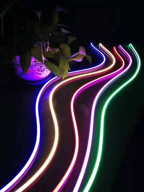
Different areas of the same project receive different UV intensity. Aging rates vary. The result is:
- Color temperature shift
- Brightness differential
- Uneven emission
Many engineers suspect LED binning issues. Actually, the problem comes from the outer material system. Optical material degradation rate has exceeded LED depreciation rate. The silicone is failing faster than the chips.
For high-altitude installations or equatorial regions, we must use molecular-level UV stabilizers, not just surface treatments. The difference becomes obvious after 10,000 hours of continuous exposure. Standard UV inhibitors might reduce yellowing by 30%. High-molecular stabilizers can reduce it by 80%. That's the difference between replacement after 2 years versus 5+ years of consistent performance.
How Does Bending Radius Affect Long-term Reliability?
Many projects assume that if a product can bend, it can bend indefinitely. This is completely wrong. Short-term bending causes no issues. Long-term small-radius positioning creates persistent stress. The internal PCB continuously bears mechanical load. This eventually causes:
- Copper foil fatigue
- Solder joint cracking
- Localized dark zones
The minimum bending radius specification is not about whether the product can physically bend—it's about the maximum stress the internal structure can withstand over 50,000 hours without fatigue failure at the solder joints.
Why Failures Occur at Design Features, Not Straight Runs
I've analyzed dozens of failure cases. Almost all occur in curved sections, not straight runs. Why? Because structural lifespan ends before LED lifespan. The mechanical design fails before the electronics fail.
For architectural applications, I now specify maximum bending as 10x the product diameter for permanent installations. For temporary installations under 1000 hours, we can use 5x diameter. Below that, we use rigid corner pieces instead of bending the flexible section. This single change reduced field failures by over 70% in our recent projects.
The physics are straightforward. When you bend a 16mm diameter product to an 80mm radius, the outer surface stretches approximately 15%. The inner surface compresses approximately 15%. At the neutral axis, there's no strain. But the PCB position is rarely at the exact neutral axis. Even 2mm offset means the copper traces experience continuous tensile or compressive stress. After 10,000 thermal cycles, micro-cracks form. After 20,000 cycles, those cracks propagate to solder joints. After 30,000 cycles, electrical connection fails.
What Makes IP68 Rating Insufficient for 360° Products?
IP68 certification tells you the product doesn't leak water today. It cannot tell you whether it will still be waterproof after three years. For 360° structures, the real danger is microcracks that form after material aging. These cracks are invisible to the human eye. But they're sufficient to create moisture penetration pathways.
True environmental durability requires testing UV stability, thermal aging performance, compression set, and temperature-humidity cycling—not just submersion testing for IP certification.
Why High-UV Regions Need Different Material Standards
I worked on a coastal resort project two years ago. The client insisted on IP68 products for underwater pool lighting. We provided certified IP68 neon flex. After 8 months, several sections started showing intermittent failure. We extracted and analyzed the failed units. The silicone surface had developed microscopic cracks from combined UV, chlorine, and thermal stress. Water vapor migrated through these pathways. Condensation formed inside the silicone tube. Eventually moisture reached the PCB.
The IP68 test only validates immediate water resistance. It doesn't predict long-term material integrity under combined environmental stressors. For coastal or high-UV installations, we now require:
- 2000+ hours QUV accelerated aging
- Salt spray resistance testing
- Thermal shock cycling (-40°C to +80°C)
- Compression set less than 25% after 1000 hours at 70°C
Standard IP68 products might pass initial testing but fail these extended protocols. The cost difference is about 15%. The failure rate difference is over 60%.
Why Do Adhesive Systems Fail After Temperature Cycling?
Many projects have perfect installations. After the first hot season, entire sections start debonding. Most people blame installation error. I've found the real cause is long-term migration reactions between adhesive systems and silicone compounds. This leads to:
- Reduced adhesion strength
- Surface tackiness
- Accelerated yellowing
Adhesive failure in 360° installations is rarely immediate—it's a progressive chemical incompatibility that manifests after 500-1000 hours of thermal cycling, making proper material compatibility testing essential before large-scale deployment.
Why Lab Testing Misses Real-world Failures
This type of problem is extremely difficult to detect in short-term lab testing. Yet it's one of the most common outdoor failure modes. The issue is plasticizer migration. Most silicone compounds contain small amounts of plasticizers for processing. Over time, especially at elevated temperatures, these plasticizers migrate to the surface. When they contact certain adhesive chemistries, they interfere with crosslinking.
I now require 1000-hour adhesion testing at 70°C before approving any mounting system. We apply the adhesive to actual production silicone samples. We cycle temperature between 20°C and 70°C every 24 hours. After 1000 hours, we measure peel strength retention. Acceptable systems maintain at least 80% of initial adhesion. Failing systems drop below 50%, and some catastrophically debond during testing.
For critical installations, we also conduct plasticizer extraction analysis. We measure migration rates under accelerated aging. Products with excessive plasticizer content get rejected regardless of initial performance.
How Do You Control Color Consistency Across Large Projects?
Large-scale projects must lock in optical material specifications and LED binning. 360° products are extremely sensitive to color variation. Why? Because viewing angles cover all directions. Even slight color temperature shift becomes dramatically amplified at night.
Color consistency in 360° installations requires three-level control: LED bin tolerance within 3-step MacAdam ellipse, silicone transmittance variation under 2%, and diffusion material batch consistency verified through spectrophotometer testing before production.
Why Batch Control Matters More Than Specifications
I managed a university campus lighting project last year. We specified 3000K CCT with 3-step MacAdam tolerance. The manufacturer confirmed compliance. During installation, we noticed slight color differences between building facades. The variation was within specification. But when all sections illuminated simultaneously at night, the color banding was obvious.
We investigated and found three contributing factors:
- LED bins were within tolerance but from different production months
- Silicone batches had 3% transmittance variation (within supplier spec)
- Diffusion additives came from two different raw material lots
Individually, each variation was acceptable. Combined, they created visible non-uniformity. We now require:
- Single LED bin for projects over 500 meters
- Single silicone extrusion batch for projects over 200 meters
- Spectral distribution testing on every 50-meter production lot
- Sample approval from actual production material, not pre-production samples
The additional cost is approximately 8%. The elimination of color complaints is 100%.
Conclusion
Choosing Neon Flex 360 LED Lights is not about achieving spectacular visual effects today. It's about ensuring that optical systems, material systems, and structural systems remain balanced over tens of thousands of operating hours. True long-term success requires treating these products as complete engineering systems, not just brighter lighting alternatives.