
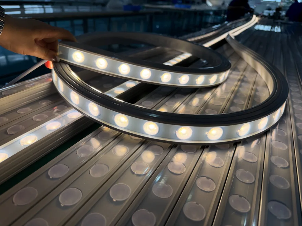
If you choose LED Neon Profiles, the project might fail two years later. Not because the LEDs stop working. But because the entire structure system starts breaking down. I learned this the hard way after watching a $200,000 façade installation begin cracking within six months. Let me show you what actually matters.
LED Neon Profiles aren't just lighting accessories. They are long-term structural systems that must survive thermal stress, mechanical stress, environmental aging, and material compatibility issues. Most project failures trace back not to LED quality, but to how the profile system interacts with mounting structures, environmental conditions, and time. Because when profiles fail, you don't just replace a light strip—you dismantle and reinstall entire sections.
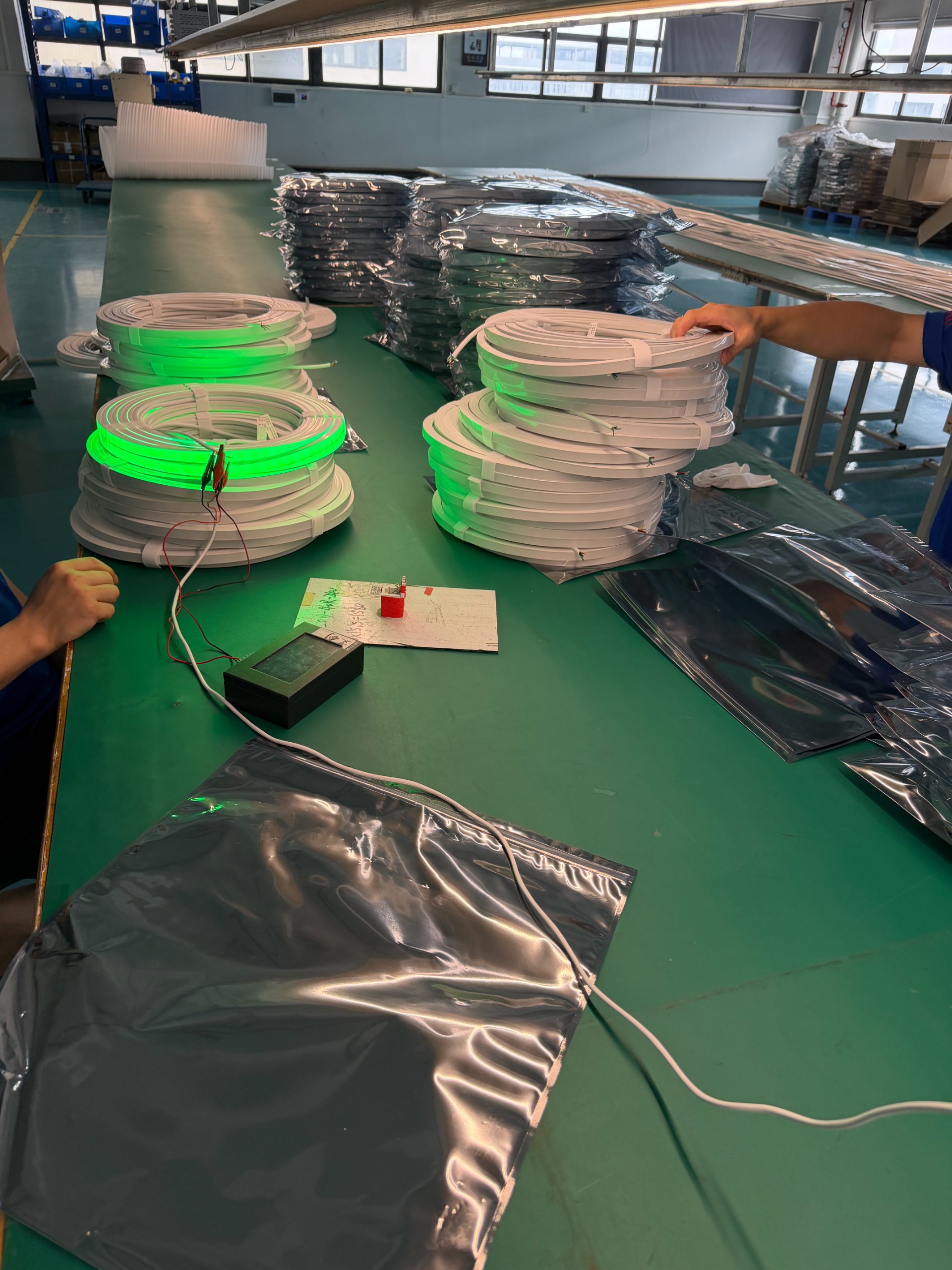
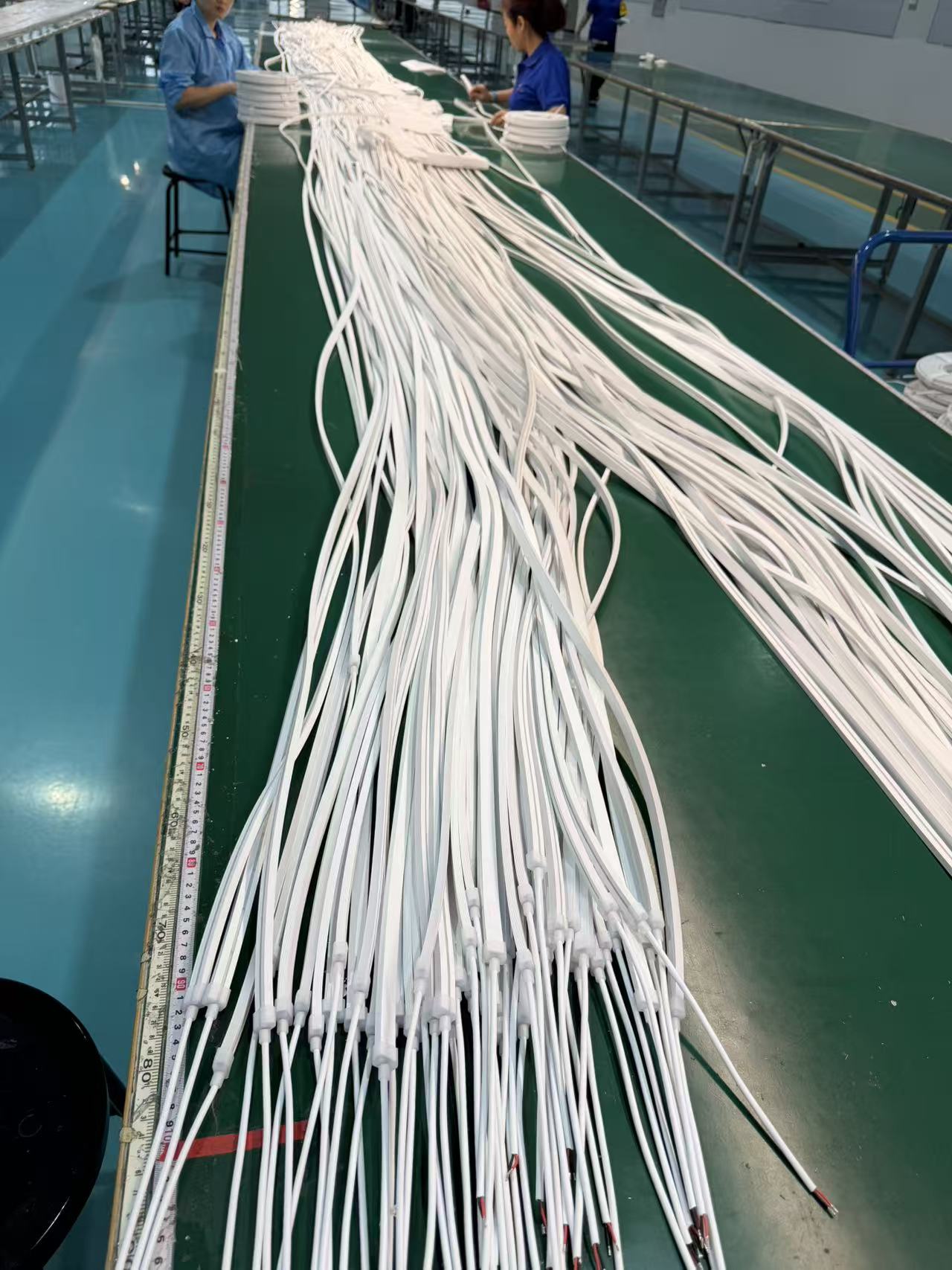
At Shenzhen Alister Technology Limited, we manufacture silicone neon flex systems for global architectural projects. I have seen hundreds of installations. Some still look perfect after five years. Others fail within months. The difference is rarely about product quality. It is always about understanding what LED Neon Profiles actually do in real-world conditions.
What Makes LED Neon Profiles Different from Standard Light Strips?
Most people think LED Neon Profiles are just protective covers. They see uniform light distribution. They notice the clean installation finish. They appreciate the premium appearance. These are product-level benefits.
LED Neon Profiles are structural systems engineered to manage thermal expansion, material compatibility, UV degradation, and mechanical stress over thousands of operating cycles. The profile determines how the entire system responds to environmental forces—not just today, but three years from now when temperature cycles have stressed every joint and connection point.
The Real Engineering Challenge
Several years ago, I worked on a high-end commercial complex exterior lighting project. The design team selected LED Neon Profiles for the façade. The reasons seemed obvious:
- Continuous light emission
- No visible LED dots
- Clean architectural lines
- Beautiful installation result
Sample phase performance was flawless. Brightness was uniform. Color temperature was consistent. Structure felt solid. All waterproofing tests passed. Project acceptance went smoothly.
Problems appeared during the first summer after installation. The sun-facing side of the building experienced sustained high temperatures. The metal substrate reached 70°C. Every day brought a complete thermal cycle. Daytime heating. Nighttime cooling.
Six months later, slight waviness appeared in some sections. After one year, corner areas showed brightness anomalies. Small cracks began forming. Then the rainy season arrived. Cracks became water infiltration channels. Local LED strip sections failed completely.
The immediate reaction was obvious: bad profile quality. But analysis revealed something different. The design used fully rigid mounting structures. No thermal expansion allowance existed anywhere. Profiles were locked tightly against aluminum structures. But silicone, aluminum, and PCB boards have completely different thermal expansion coefficients.
Stress from thermal cycling had nowhere to go. It concentrated at:
- Corner joints
- Mounting clip locations
- Connection points
Cracks were just the final symptom. The actual failure started the day of installation.
| System Component | Thermal Expansion Coefficient | Expansion at 50°C Change |
|---|---|---|
| Silicone Profile | 300 × 10⁻⁶ /°C | 1.5mm per meter |
| Aluminum Structure | 23 × 10⁻⁶ /°C | 0.12mm per meter |
| PCB Board | 17 × 10⁻⁶ /°C | 0.09mm per meter |
When materials expand at different rates but are locked together, internal stress builds continuously. Over hundreds of cycles, this stress must release somewhere. Usually at the weakest structural points.
Can Standard Installation Methods Handle Long-Term Environmental Stress?
This is the most common mistake in LED Neon Profile projects. People treat profiles as simple housings. They focus on achieving a clean installation finish today. They ignore what happens after two years of environmental exposure.
Standard rigid mounting creates stress concentration points that gradually compromise structural integrity. True durability requires understanding how thermal cycles, UV exposure, and material aging interact over thousands of operating hours. The mounting system must allow controlled movement while maintaining alignment and waterproofing.
The Hidden Material Compatibility Problem
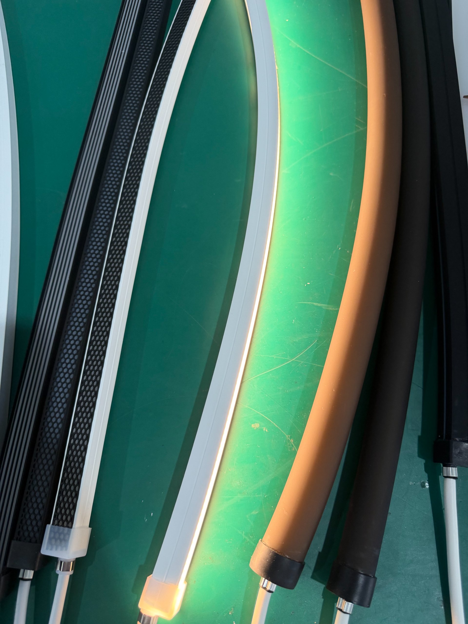
Another invisible issue appears frequently. Projects use high-quality silicone profiles. Premium LEDs. Quality structural adhesives. Each component passes individual testing. But combined together, they show yellowing, tackiness, or adhesive failure within months.
The cause is not complicated. Different material systems undergo long-term migration reactions. Some adhesives release low-molecular compounds that gradually penetrate silicone structures. Over time, this causes:
- Surface tackiness
- Transparency reduction
- Accelerated yellowing
- Decreased bonding strength
Short-term laboratory tests rarely detect this. But real environments allow continuous accumulation. By the time problems appear, projects have usually been delivered for over a year. This creates the most frustrating warranty situations. Local repairs are impossible. Complete replacement is the only solution.
Material Selection Requirements
At our Shenzhen factory, we conduct accelerated aging tests that simulate three years of outdoor exposure in 90 days. We test silicone profiles with multiple adhesive systems. We measure:
- Weight change (volatile compound loss)
- Hardness variation (plasticizer migration)
- Transparency retention (yellowing resistance)
- Bonding strength degradation
Many material combinations that appear perfect initially show significant changes after 1000 hours of 85°C/85% humidity exposure combined with UV radiation. These are the combinations that will fail in real projects.
| Test Condition | Duration | Failure Indicators |
|---|---|---|
| High Temperature | 1000h at 85°C | Hardness change >10 Shore A |
| UV Exposure | 1000h UV-A | Yellowing index Δb* >5 |
| Thermal Cycling | 500 cycles -40°C to +80°C | Crack formation, delamination |
| Salt Spray | 1000h neutral salt fog | Surface degradation, adhesion loss |
Does Higher Profile Hardness Mean Better Durability?
This is a critical misunderstanding. Many people assume harder silicone profiles are more durable. They think higher Shore hardness means better performance. This is wrong for outdoor installations.
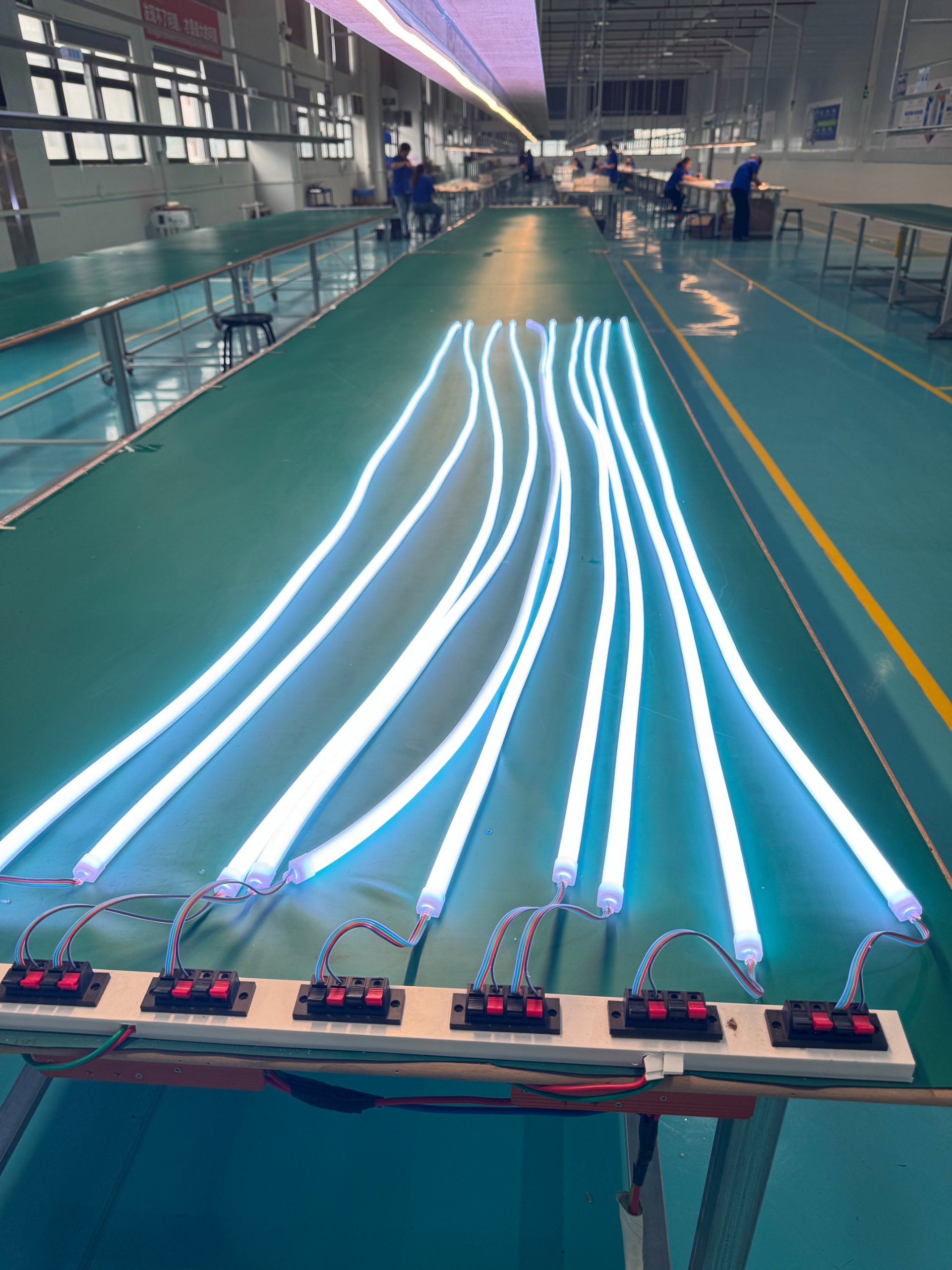
Profile hardness must match installation orientation, mounting spacing, environmental temperature range, and structural loading. Too hard creates stress concentration and microcracking. Too soft causes creep deformation and sagging. Optimal hardness depends on specific application conditions, not a universal "harder is better" rule.
The Hardness Calculation
For vertical installations on building facades, we calculate required hardness based on:
- Mounting interval distance
- Profile weight per meter
- Maximum ambient temperature
- Expected service life
A 16×16mm profile with 500mm mounting intervals operating in 60°C environments needs approximately 70-75 Shore A hardness. At 75 Shore A, the profile maintains dimensional stability without excessive stress concentration.
The same profile in horizontal installation with 1000mm intervals needs different hardness. Gravity creates continuous downward force. Too soft causes visible sagging. But if hardness exceeds 80 Shore A, thermal cycling creates internal stress that eventually forms microcracks.
We use finite element analysis to model stress distribution under different conditions. This reveals optimal hardness ranges for specific applications.
Temperature Impact on Material Properties
Silicone mechanical properties change significantly with temperature. A profile that feels rigid at 20°C becomes much softer at 60°C. At -20°C, the same material becomes brittle. Design hardness must account for the full operating temperature range.
High-quality food-grade silicone maintains consistent properties across -40°C to +60°C. But cheaper formulations show dramatic property changes. At 60°C, inferior silicone may soften to the point of deformation. At -20°C, it may crack under normal handling stress.
How Does IP Rating Relate to Actual Waterproof Lifespan?
IP67 and IP68 ratings only indicate waterproofing performance at the time of testing. They say nothing about performance after three years of environmental exposure. This is perhaps the most misleading specification in LED Neon Profile datasheets.
True waterproofing durability depends on UV stability, thermal aging resistance, ozone resistance, and compression set characteristics. Many profiles pass IP68 testing when new but lose sealing capability after hundreds of thermal cycles. The IP rating remains in the specification sheet, but actual service life has ended.
What Actually Determines Long-Term Sealing
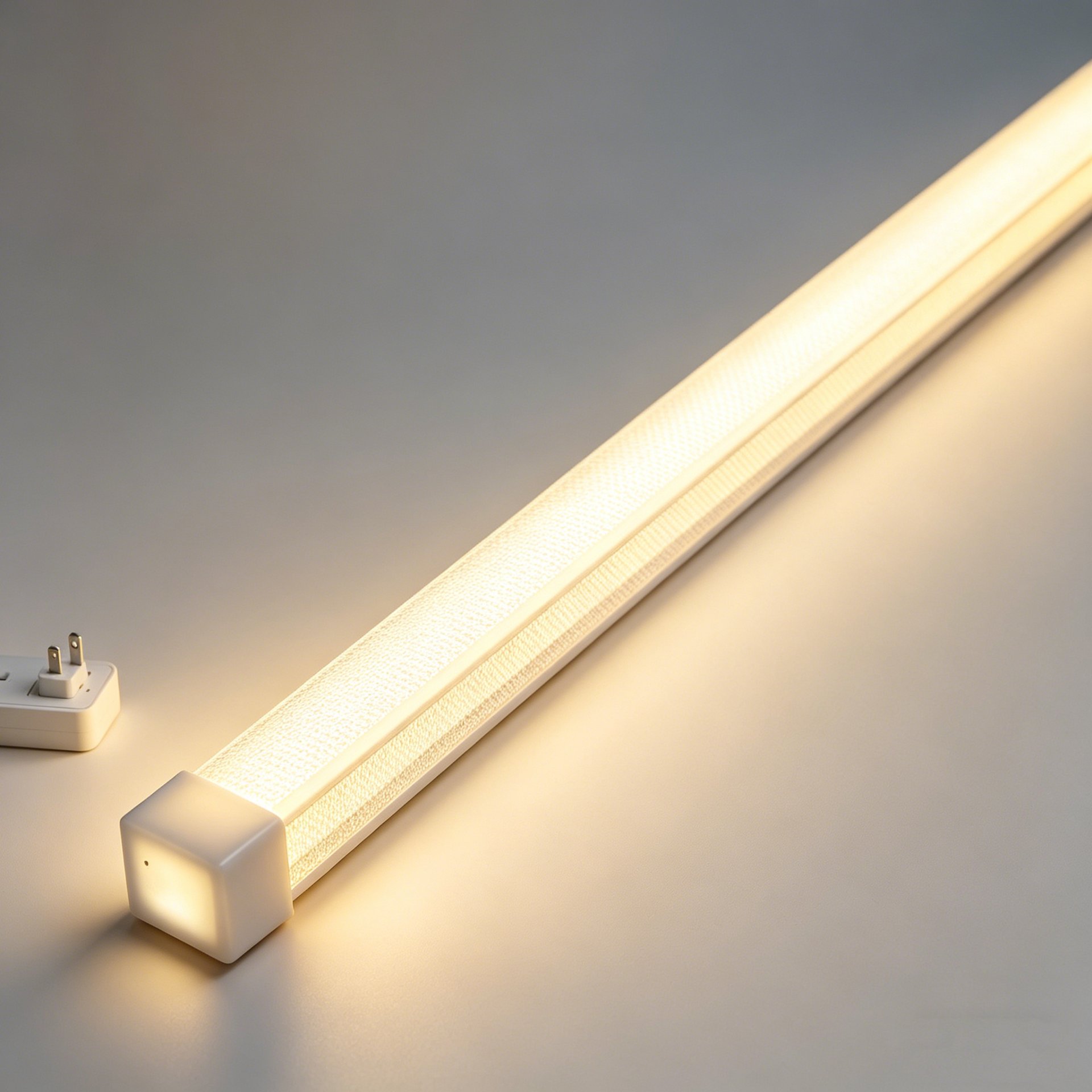
We test compression set after thermal aging. This measures how much the silicone permanently deforms after being compressed at high temperature. A profile with good initial sealing but high compression set will gradually lose contact pressure at sealing interfaces.
After 1000 hours at 70°C under 25% compression, quality silicone shows less than 15% permanent deformation. Inferior materials show 30-40% permanent deformation. This means after one hot summer, sealing pressure has decreased by one-third or more.
Water ingress often occurs not through obvious damage, but through gradual sealing degradation at:
- End caps
- Connection joints
- Mounting clip contact points
- Cable entry locations
These are precisely the locations experiencing maximum compression and thermal stress.
UV Degradation and Waterproofing
UV radiation doesn't just cause yellowing. It breaks down polymer chains in silicone. This reduces elasticity and increases brittleness. A profile that survives 500 thermal cycles when new might crack after 200 cycles following one year of UV exposure.
We add UV stabilizers to our silicone formulation. But stabilizer concentration affects cost. Low-cost profiles use minimal stabilizers. They pass short-term UV testing but degrade rapidly in real sunlight.
High-altitude installations face particularly intense UV exposure. A profile suitable for sea-level urban environments may fail quickly at 2000m elevation where UV intensity is 20-30% higher.
Why Do Large-Scale Projects Show Visual Inconsistencies After Installation?
I frequently see this problem. Projects install hundreds of meters of LED Neon Profile. Initial appearance is perfect. Uniform brightness. Consistent color. Clean lines. Six months later, visible banding appears. Some sections show slightly different brightness. Others display subtle color variations.
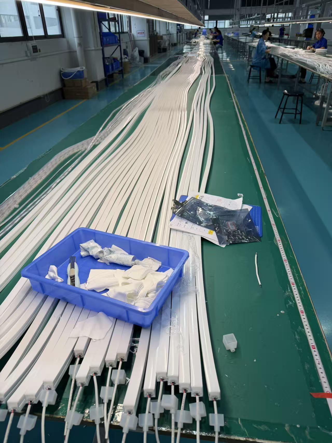
Visual inconsistencies in large installations rarely originate from LED quality variations. They result from extrusion process inconsistencies in the profile itself. Wall thickness fluctuation, uneven diffusion layer distribution, or unstable material mixing create optical variations that become visible across long installation distances.
The Extrusion Quality Challenge
Silicone extrusion requires precise control of:
- Material temperature (±2°C tolerance)
- Extrusion speed (±3% variation)
- Die temperature distribution
- Crosslinking time and temperature
- Post-cure conditions
Small variations in any parameter affect final optical properties. A 0.2mm wall thickness variation creates visible brightness differences. Uneven diffusion particle distribution causes light and dark bands.
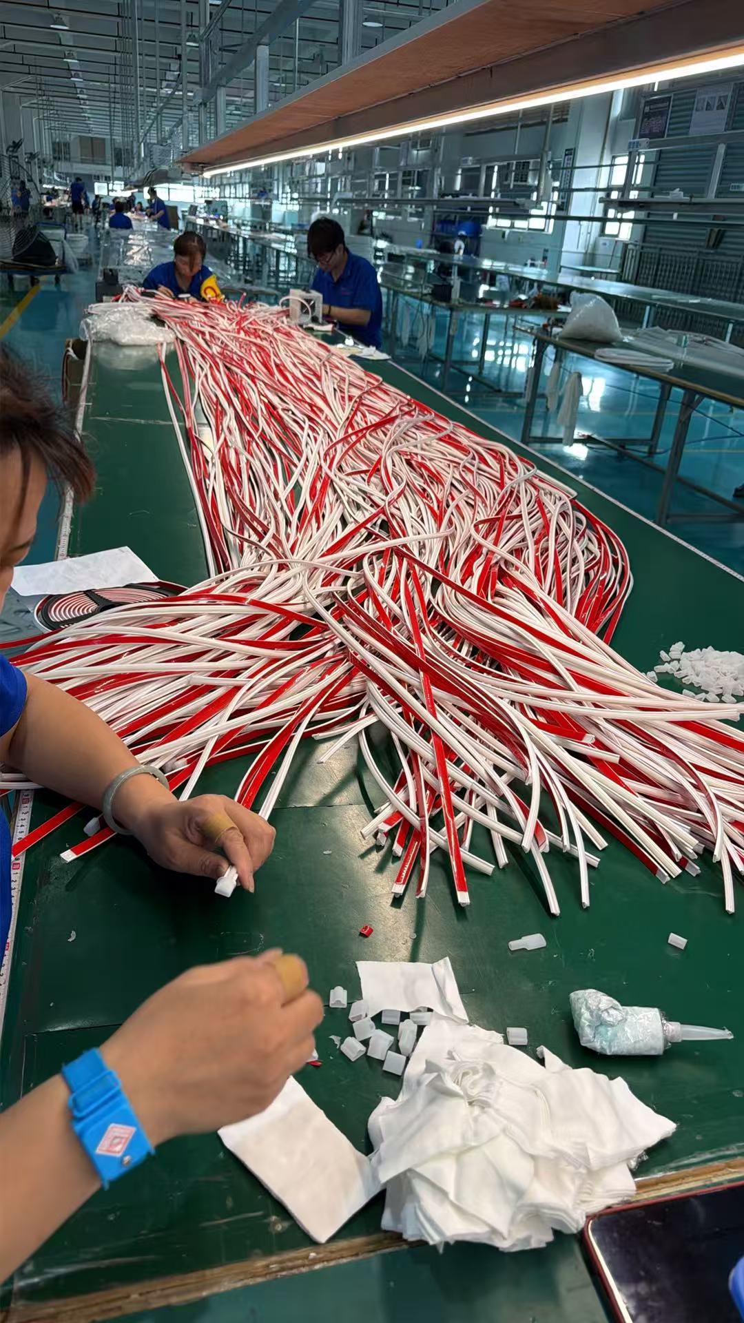
At our factory, we use laser measurement systems during extrusion. Every meter is checked. Wall thickness deviation must stay within 0.1mm. Diffusion layer concentration is verified through sample testing every 30 minutes. If variation exceeds tolerance, production stops for adjustment.
But not all manufacturers maintain these standards. Cost pressure drives some to accept larger tolerances. The profiles still function. LEDs still light. But installed across 50 meters of building facade, inconsistencies become obvious.
Color Temperature Perception Shifts
Even with identical LEDs, profile optical properties affect perceived color temperature. A profile section with slightly thicker walls appears warmer. Thinner sections appear cooler. Across long runs, this creates visible color banding.
This is particularly problematic with neutral white (4000K-4500K). Human eyes are extremely sensitive to color temperature variations in this range. A shift of just 100K becomes noticeable. The same variation in 3000K warm white or 6000K cool white is less obvious.
We specify LED binning within 3-step MacAdam ellipses for architectural projects. But profile consistency matters equally. Both must be controlled to achieve uniform appearance.
Must All Mounting Systems Include Thermal Expansion Compensation?
Yes. Absolutely. Without exception. This is non-negotiable for any professional installation. Thermal expansion is not optional. It is physics. Materials expand when heated. They contract when cooled. If the structure doesn't accommodate this movement, something will fail.
Long-distance LED Neon Profile installations must include thermal expansion compensation in the mounting system. When runs exceed 10 meters, temperature changes produce dimensional variations that far exceed typical tolerances. Without controlled movement paths, stress concentrates at joints, corners, and cable exits—precisely where failures typically begin.
Calculating Required Expansion Allowance
Silicone's thermal expansion coefficient is approximately 300×10⁻⁶ per °C. For a 30-meter run experiencing a 40°C temperature swing (common for sun-exposed facades), total expansion is:
30m × 40°C × 300×10⁻⁶ = 360mm or 36cm
Thirty-six centimeters. Over half the length of a ruler. This expansion must go somewhere. If the mounting system doesn't provide a path, internal stress builds until something breaks.
We design expansion joints every 5-10 meters depending on:
- Expected temperature range
- Profile size and flexibility
- Mounting method rigidity
- Structural substrate material
Expansion joints use sliding mounting clips that allow longitudinal movement while maintaining vertical alignment. Electrical connections must also accommodate movement through flexible cable loops.
The Corner Problem
Corners are the most challenging locations. Linear expansion along two perpendicular runs creates complex stress patterns at the intersection. Right-angle corners need special attention. We use flexible corner pieces that allow both rotation and linear movement.
Rigid corner connections work fine in climate-controlled indoor installations. Outdoor building facades need engineered flexibility. Otherwise corners show the first cracks within six months.
Conclusion
Choosing LED Neon Profiles is not about getting better light today. It is about maintaining structural integrity for five years while materials, environment, and stress interact continuously. Because when profiles fail, you don't replace a component—you rebuild entire sections at costs far exceeding original installation. That is why we engineer systems, not just products.