

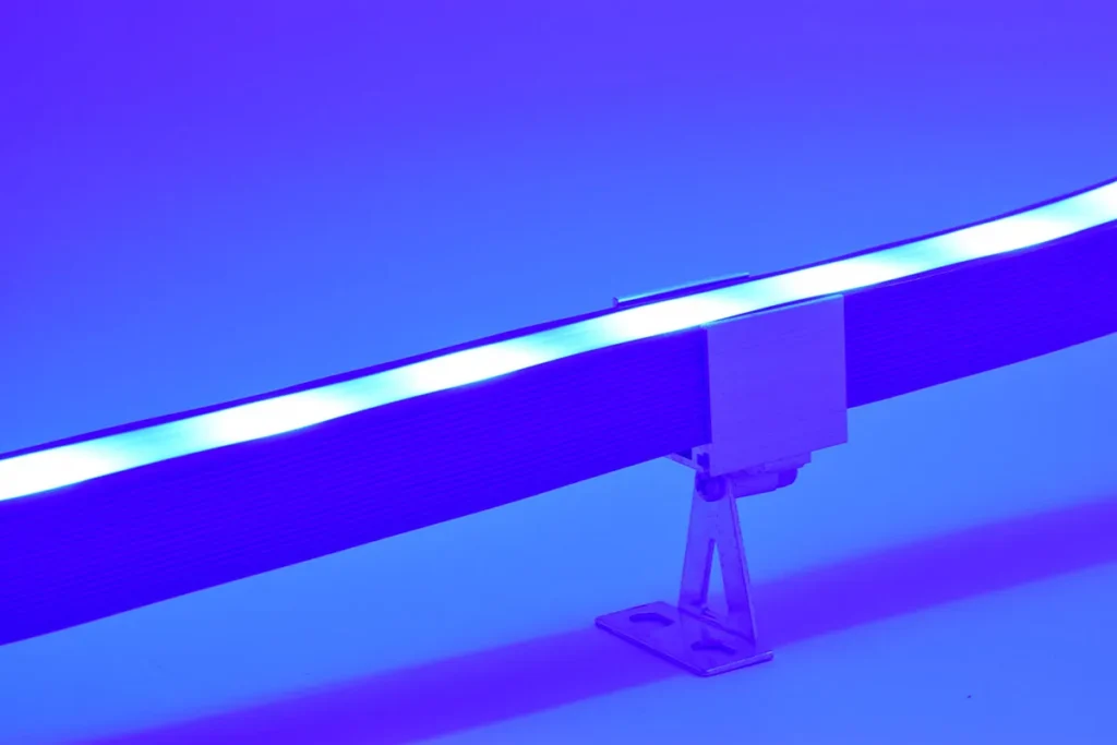
In commercial lighting and architectural projects, Commercial LED Strip Lights are almost the most common foundational light source. They're widely applied in shopping mall ceiling contours, hotel ambiance lighting, retail display windows, building facade accents, landscape guide systems, and chain store standardized lighting. Because they seem "simple and standard," project teams often underestimate their risk. But from engineering post-mortems, the real danger isn't the light strip itself—it's how teams misjudge the strip's role in the system, treating a "system component" as just "procurement material." This misjudgment causes design revisions, site rework, acceptance disputes, and cost overruns, even when every parameter is technically correct.

You might think choosing the right LED strip is the key to success. But what if I told you that most project failures happen before you even place the order? Let's break down where things really go wrong.
What's the Biggest Decision Mistake Teams Make with Commercial LED Strip Lights?
When projects kick off, I've noticed something interesting: procurement teams, lighting designers, general contractors, installation crews, and brand owners all tend to reach the same conclusion without much debate. They assume LED strip lights are just "replaceable standard materials." So the decision process becomes purely transactional—compare specs, check prices, verify parameters, confirm delivery dates. On paper, this looks perfectly reasonable. LED strips are modular, cuttable, connectable, and seemingly universal. Naturally, everyone thinks: different suppliers won't differ much, matching parameters means interchangeability, cost control takes priority.
But here's the trap: Commercial LED Strip Lights don't exist in isolation within a project. They're embedded in a complete system—building structures (light troughs, suspended ceilings, curtain walls), electrical systems (drivers, voltage, circuits), spatial systems (reflection, materials, distances), and visual systems (continuity, hierarchy, rhythm). The light strip is the "execution terminal" of this system. Yet project management treats it only as a "procurement item."
Why This Judgment Looks Correct but Causes Chaos
I've seen this pattern repeat across dozens of projects. The logic chain seems airtight: LED strips are standardized → specifications are universal → suppliers are interchangeable → cost is the priority. The problem emerges when installation begins. You start seeing:
1. Lighting effects that fail despite perfect parameters. Brightness meets spec. Color temperature matches. Power rating is correct. Yet the space looks flat—no depth, no focal points, no visual rhythm. The issue isn't the strip; it's the missing system design.
2. Mid-project design overhauls. Site teams discover the strip conflicts with structural elements. This triggers light trough modifications, ceiling reconstruction, and complete design breakdowns.
3. Massive site rework. Strips can't lay continuously. Corner treatments fail. Circuit routing doesn't match. The project becomes "improvised design on-site."
4. Validation disputes with no clear fault. The designer says "the effect is wrong." The installer says "we followed the drawings." Procurement says "specifications match." The supplier says "product complies." Everyone's technically correct, yet the project fails.
5. Distorted project cost structure. Material costs drop as a percentage, but installation, adjustment, and rework costs explode beyond projections.
The core mistake is this: design assumes "the strip system operates in a unified environment," but reality is "multiple systems stitched together." Sample validation happens in single spaces with standard light troughs and controlled conditions. Real sites involve multiple building structures, multiple installation teams, multiple material interfaces. Nobody catches this mismatch until it's too late.
One Engineering Disaster That Reveals the Pattern
Let me walk you through a project that seemed bulletproof until it wasn't. This was a high-end commercial complex interior public space project. The design objective was clean: use Commercial LED Strip Lights to create a "continuous light environment system" across the atrium ceiling contours, shop perimeter light troughs, and circulation pathway guides. The design team defined unified color temperature, unified strip specifications, unified control systems. The logic was crystal clear—use standardized strips to build a unified spatial light language.
Phase One: Design Approval
The design documentation looked flawless. Everyone signed off. The specifications were tight: single model type, consistent parameters across all zones, centralized control architecture. The procurement team ran multiple supplier rounds and locked in the winning bid. Unit price was competitive. Delivery schedule aligned perfectly. Base parameters met all requirements.
Phase Two: Sample Validation
Sample testing happened in a controlled environment—small-scale light trough section, indoor standard lighting, single-space setup. The effect was excellent. Green light given. The project moved into execution.
Phase Three: Installation Begins
This is where reality diverged from drawings. The first issue was spatial continuity breakdown. Different zones had different light trough structures—varying widths, depths, and materials. Light output looked inconsistent across zones despite identical strips. The second issue was visual rhythm collapse. The design called for "continuous light bands," but the site showed brightness jumps, visual breakpoints, and inconsistent light band layering. The third issue was electrical circuit mismatches. Multiple zones had different voltage drops and supply path lengths, causing brightness inconsistencies.
How Did This Happen Step by Step?
The error wasn't in execution—it was in the foundational assumption. The design phase assumed "the strip system operates in a uniform environment." But the construction reality was "multiple systems stitched across varying conditions." Sample validation tested a single space with a single structure and standardized trough. The actual site involved multiple architectural structures, multiple construction crews, and multiple material interfaces. Nobody modeled this complexity upfront.
Why Didn't Anyone Catch This Earlier?
Because validation environments were sanitized simulations. Testing happened in ideal conditions—controlled spaces, isolated segments, perfect power supply. Real projects involve:
- Varying ceiling heights across zones
- Mixed material reflectivity (glass, stone, metal, wood)
- Uneven electrical infrastructure
- Multiple installation teams with different skill levels
- Phased construction timelines creating interface gaps
None of this appeared in the sample test.
The Final Consequences
Parts of the system required light trough reconstruction. Electrical distribution needed redesign across multiple zones. The schedule slipped. Costs overran projections. Spatial lighting design went back to the drawing board. But here's the key point: no single supplier violated any specification. No contractor failed to follow drawings. No parameter was out of tolerance. The failure occurred at the system assumption layer.
This pattern repeats constantly. Teams treat Commercial LED Strip Lights as a low-complexity, plug-and-play component. But these strips interface with structural, electrical, spatial, and visual systems. Ignoring this interdependency is where projects lose control.
The Hidden Traps in Commercial LED Strip Specification Sheets
Let me show you where specification sheets create false confidence. These aren't lies—they're incomplete truths that project teams misinterpret.
Trap One: Unified Parameters ≠ Unified Space
Specification sheets typically state: color temperature consistent, power rating consistent, brightness level consistent. But they don't define how these parameters behave across varying spatial structures, observation distances, or reflective environments. The result? Parameters match perfectly, yet spatial effects look completely inconsistent. I've walked through projects where every measurement validated, but clients rejected the installation because "it doesn't look right."
Trap Two: IP Rating ≠ System-Level Protection
IP ratings apply to the strip body itself. But projects also involve connectors, corner assemblies, power supplies, and driver systems. These junction points are where failures actually occur. A strip rated IP68 doesn't guarantee the installed system achieves IP68—especially when installers use non-rated connectors or create unsealed penetrations.
Trap Three: Cuttable ≠ Systemically Integratable
"Cuttable LED Strip" means you can trim it to length. It doesn't mean you can freely route it across arbitrary structural geometries, maintain continuous operation across multiple spaces, or achieve seamless visual transitions at every corner and junction. Cutting flexibility creates a false sense of installation adaptability.
Trap Four: Sample Approval ≠ Project Approval
Sample validation typically ignores real operating length, actual power distribution architecture, and authentic environmental conditions. A 50cm sample strip in a test box behaves completely differently than a 30-meter continuous run with multiple bends, junctions, and driver zones. Yet project teams approve samples and assume this validates the entire installation.
Trap Five: Brightness Compliance ≠ Visual Achievement
Brightness is a single-point metric measured at one position under controlled conditions. Spatial visual quality is a system outcome involving light distribution, material interaction, contrast ratios, and human perception across dynamic viewing angles. A strip can meet every brightness specification and still produce a visually poor result.
Trap Six: Single-Segment Testing ≠ Multi-Segment Systems
LED strips behave completely differently in long-distance system applications. You encounter voltage drop across length, non-uniform brightness distribution, and visual rhythm changes that don't appear in short test segments. Specification sheets rarely cover performance degradation across multi-segment installations. I've seen projects where the first three meters look perfect, but the next ten meters show visible dimming that no spec sheet predicted.
Trap Seven: Drive Compatibility Claims Without System Context
Many strips claim "universal driver compatibility." But real projects involve specific driver models, dimming protocols, control systems, and circuit topologies. Compatibility in theory doesn't guarantee seamless integration in practice. I've seen installations where strips and drivers were both "correct" individually but created flicker and instability when combined in the actual electrical architecture.
Trap Eight: Installation Guidance That Ignores Real Constraints
Specification sheets often include installation instructions based on ideal scenarios—flat surfaces, accessible routing, standard electrical access. Real projects involve curved ceilings, obstructed pathways, legacy electrical systems, and physical constraints that make "recommended installation" impossible. Yet teams design based on ideal specs, then discover on-site improvisation becomes necessary.
The fundamental issue is this: specification sheets describe product capability in isolation. Projects require system performance in complex, variable environments. The gap between these two realities is where most failures originate.
Project-Level Risk Control Strategies That Actually Work
Now let me shift to what actually prevents these disasters. I'm not talking about generic "best practices"—I'm talking about specific, executable risk controls that I've seen work across large-scale projects.
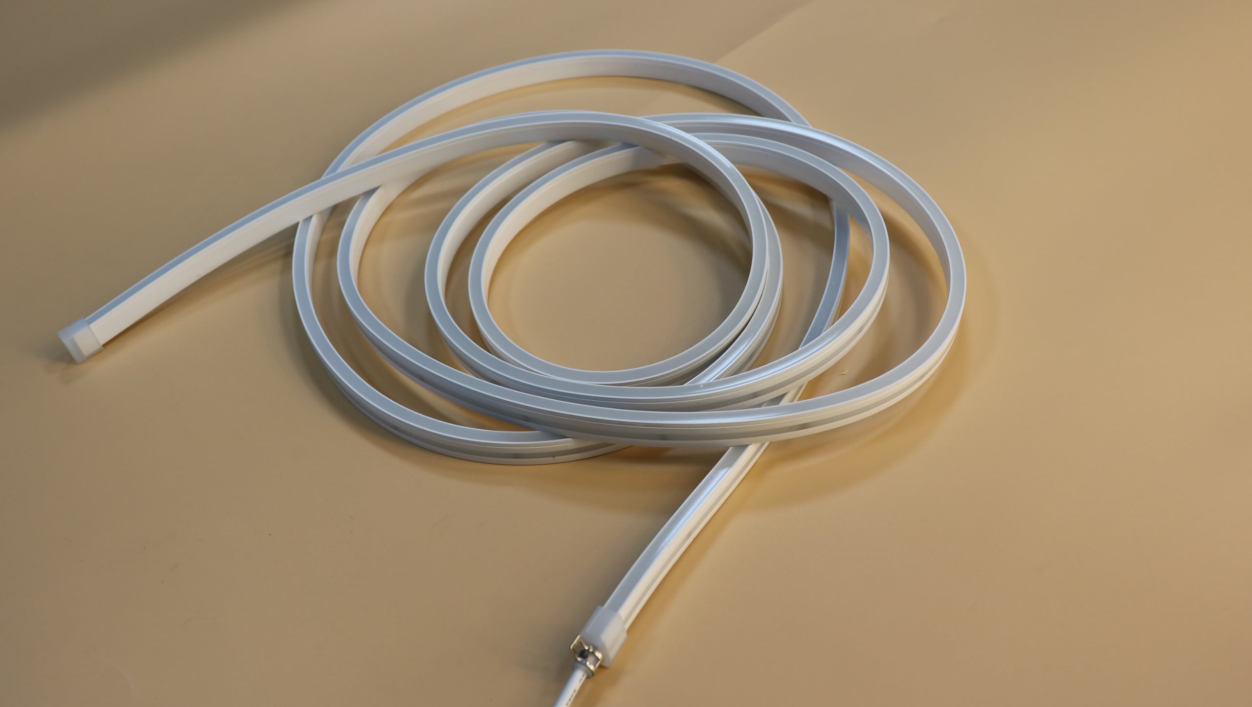
1. Redefine LED Strips from "Material" to "System Component"
At project initiation, force this explicit definition: LED strips are components of spatial lighting systems, not procurement materials. This changes everything downstream. It shifts responsibility from procurement optimization to system integration. It requires design teams to model how strips interact with structures, electrical systems, and visual hierarchies—not just specify a product.
2. Establish Structure-Light Integrated Design Review
Every LED strip installation must be bound to specific structural elements, installation nodes, and power routing paths before design approval. Create a matrix that maps each strip segment to its physical light trough, electrical circuit, and structural interface. This catches conflicts before fabrication begins. I've seen this single step eliminate 60-70% of on-site rework.
3. Mandate On-Site Structural Simulation
Sample validation must include actual light troughs, actual installation lengths, and actual corner conditions. Build a 1:1 physical mockup in the real project environment—same materials, same viewing distances, same ambient light. Test for at least 72 hours to capture different lighting conditions. Don't approve samples in lab environments that don't represent site reality.
4. Implement Multi-Zone Consistency Testing
Don't test single segments in isolation. Test long-distance runs, multi-circuit systems, and cross-zone stitching. Simulate voltage drop across maximum cable runs. Verify brightness uniformity at the furthest point from power supply. Check visual consistency across different viewing angles and material backgrounds. This reveals system-level issues that single-segment testing misses.
5. Standardize Electrical System Design Parameters
Define explicit rules for circuit run lengths, voltage drop control strategies, and driver zoning. For example: no single circuit exceeds 15 meters, maximum voltage drop capped at 5%, each zone uses dedicated drivers with matched dimming protocols. Make these non-negotiable design constraints, not optimization variables. Document them in electrical drawings, not just in specs.
6. Create Pre-Construction Light Pathway Audits
Before installation begins, walk the entire light path route. Verify that light continuity is physically achievable, that no structural obstructions create breakpoints, and that no visual conflicts exist with other building systems. Use this audit to create an installation sequence plan that accounts for access constraints, coordination requirements, and quality checkpoints.
7. Bind Batches to System Zones
Different spatial zones must use strips from the same production batch. Prohibit mixing batches across visually continuous runs. Create a batch tracking system that maps serial numbers to installation locations. This prevents subtle color temperature or brightness variations that occur across production batches, even when specs are nominally identical.
8. Establish Cross-Discipline Joint Signoff Mechanism
Require simultaneous approval from design team, electrical team, construction team, and client representatives at key milestones: design freeze, sample approval, first installation section, and pre-commissioning. This forces coordination before problems cascade. It also creates shared accountability—no single party can claim "I did my part" while the system fails.
9. Develop Contingency Protocols for System Adjustments
Plan for reality diverging from design. Pre-define adjustment protocols: if brightness non-uniformity exceeds X%, what's the correction procedure? If structural conflicts emerge, who has authority to approve field modifications? If batch inconsistency appears, what's the replacement trigger? Document these protocols before problems occur, not during crisis management.
10. Create Post-Installation Performance Benchmarks
Define measurable success criteria beyond parameter compliance: maximum brightness variation across zones (±10%), acceptable color temperature drift (±200K), visual continuity rating scale. Use these benchmarks for objective acceptance testing. This shifts validation from subjective opinion ("it looks wrong") to measurable performance ("zone 3 brightness is 22% below zone 1").
These controls add upfront effort. But they prevent catastrophically expensive failures. The ROI isn't in avoiding product defects—it's in avoiding system mismatches that require partial demolition and reconstruction.
Conclusion
Commercial LED Strip Lights look deceptively simple, but they're integration points where structural, electrical, spatial, and visual systems converge—and that's where control is most easily lost. The real risk isn't choosing the wrong strip; it's treating a system component as a procurement item, causing teams to miss the structural conflicts, electrical mismatches, and spatial performance gaps that only appear when systems integrate. Projects fail not because parameters were wrong, but because the foundational assumptions about "unified environments" didn't match the reality of "stitched-together systems." Risk control starts at project definition, not supplier selection.