

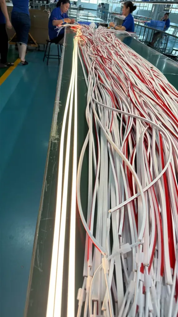
I've seen too many commercial lighting projects collapse—not because the product failed, but because decision-makers treated LED neon tubes as "just another material" instead of what they really are: a system-level engineering component.
LED neon tubes are flexible, silicone-based linear lighting systems designed to replace traditional glass neon. They're widely used in architectural facades, retail signage, and commercial interiors. But in real-world installations, they function as system boundary components—connecting design intent, structural constraints, installation logic, and procurement processes. Most project failures happen not at the product level, but at the decision-making level, where the system's boundaries are fundamentally misunderstood.
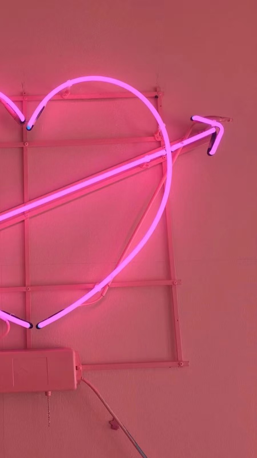
If you're a contractor, lighting designer, or procurement manager, you need to understand this: LED neon tubes don't fail in the lab. They fail when someone assumes "sample approval" equals "system validation."
What Makes LED Neon Tubes Different from Traditional Lighting Systems?
I remember sitting in a project review meeting where everyone kept nodding at the glowing sample on the table, and I kept thinking: "This is not how it's going to look on site."
LED neon tubes are not discrete fixtures—they are continuous lighting systems. Unlike traditional tube lights, they require structural integration, precise bending control, and seamless joining across multiple segments. Their flexibility is both their strength and their vulnerability, because every design decision impacts the entire installation chain.
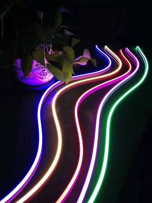
Here's what makes them fundamentally different from other lighting products:
Material Structure and Engineering Constraints
LED neon tubes use food-grade silicone extrusion, not rigid plastic housings. This means:
| Characteristic | Engineering Implication | Project Risk |
|---|---|---|
| Flexible silicone body | Can conform to curves | Stress points accumulate in complex bends |
| Continuous LED strip | Seamless light emission | Voltage drop affects distant segments |
| Modular connectors | Field-joinable sections | Visual discontinuity at connection points |
| UV-resistant coating | Outdoor durability | Performance varies across production batches |
The critical point: each of these characteristics interacts with the others. You cannot optimize one without affecting the rest.
Installation Logic vs. Product Logic
When I work with contractors, I always ask: "Are you installing a product, or are you building a system?" Most people answer "product," and that's where the problem starts.
LED neon tubes require:
- Substrate preparation before mounting
- Stress-free bending within minimum radius limits
- Aligned power distribution across zones
- Weatherproof termination at every cut point
- Color consistency validation across batches
Traditional lighting doesn't require this level of pre-installation planning. You mount a fixture, wire it, and you're done. But with LED neon tubes, the installation is the product performance.
Why Do LED Neon Tube Projects Fail Even When Samples Look Perfect?
The most dangerous moment in any LED neon tube project is when the client looks at the sample and says, "Perfect. Let's proceed."
Projects fail because stakeholders confuse "visual effect validation" with "engineering feasibility validation." A glowing 2-meter sample in controlled conditions does not prove that a 200-meter continuous system will perform consistently across multiple installation teams, structural variations, and environmental conditions.
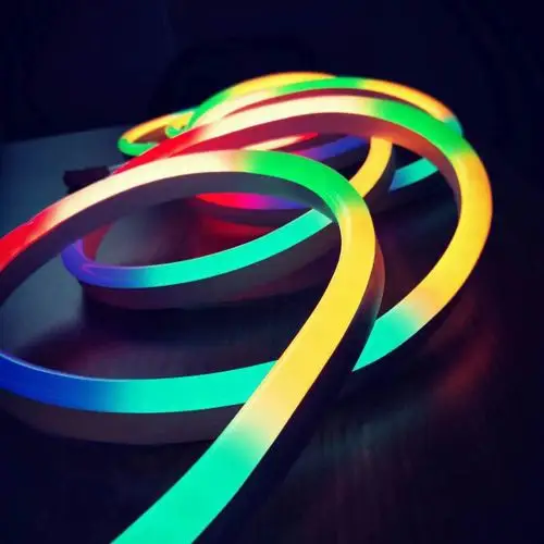
The Hidden Assumption That Destroys Projects
Every failed project I've analyzed shared the same implicit assumption:
"If the sample works, scaling it up is just a matter of quantity."
This assumption ignores three critical realities:
Reality 1: Samples are isolated systems
- Tested in ideal electrical conditions
- No structural constraints
- No joining errors
- No installation tolerances
Reality 2: Projects are continuous systems
- Hundreds of meters of interconnected segments
- Multiple production batches
- Multiple installation crews
- Cumulative structural tolerances
Reality 3: Responsibility gets fragmented
| Stakeholder | What They Think | What They Ignore |
|---|---|---|
| Designer | "Installers will figure it out" | Structural constraints |
| Installer | "Material should match design" | System adaptation requirements |
| Procurement | "We bought per spec" | System-level compatibility |
| Client | "It looked good in renders" | Real-world constraints |
No one owns the system outcome. Everyone owns a piece of the process.
A Real Project Failure: When Perfect Samples Led to Total Rework
I witnessed a flagship retail store project where this played out exactly as I've described. The brand approved a beautiful curved facade design using LED neon tubes. The sample looked flawless. The team proceeded.
Three weeks before opening, the installation was a visual disaster. Why?
The curved facade had variable radius segments. Each segment required precise bending. Each bend created stress points. Each stress point shifted the LED positioning. Each shift created visible discontinuity. The "continuous light band" became a "segmented, misaligned patchwork."
The project didn't fail because of bad products. It failed because no one asked: "How do we verify that this continuous system will behave consistently across variable structural conditions?"
The result:
- Three weeks of delay
- Complete facade rework
- Installation costs exceeding material costs by 300%
- Design intent compromised
- Blame distributed across every party
How Do Specification Sheets Create Hidden Project Risks?
I've reviewed hundreds of LED neon tube spec sheets, and I can tell you: the danger isn't what they say. It's how different people interpret what they say.
Specification sheets describe laboratory conditions, not installation realities. Parameters like IP rating, color consistency, and flexibility are tested in controlled environments. But projects exist in messy, constraint-filled real-world conditions where those parameters interact with structural variables, installation errors, and environmental factors.
The Four Specification Traps That Kill Projects
Trap 1: IP Rating Misunderstanding
Spec sheet says: "IP68 waterproof"
What stakeholders assume: "The installed system is waterproof"
What it actually means:
| Specification Scope | Installation Reality |
|---|---|
| Lab-tested immersion resistance | Does not cover field-cut terminations |
| Static sealing integrity | Does not cover installation stress points |
| Single-unit performance | Does not cover multi-segment connections |
Result: Water ingress at connection points causes localized failures six months post-installation.
Trap 2: Bendability Claims
Spec sheet says: "Flexible, minimum bend radius 50mm"
What stakeholders assume: "Can conform to any curved surface"
What it actually means:
- Can bend to 50mm radius in controlled conditions
- Does not guarantee visual consistency across compound curves
- Does not prevent stress accumulation in complex geometries
Result: Curved installations show visible "kinks" or inconsistent light distribution.
Trap 3: Color Consistency Standards
Spec sheet says: "Color consistency within ΔE<3"
What stakeholders assume: "All sections will look identical"
What it actually means:
- Consistency measured within single production batch
- Does not account for batch-to-batch variation
- Does not account for voltage drop effects over distance
- Does not account for driver variations across zones
Result: A facade shows visible "color zones" despite all materials meeting spec.
Trap 4: Testing Certifications
Spec sheet says: "Passed UL/CE testing"
What stakeholders assume: "Guaranteed to work in our application"
What it actually means:
- Product passed specific test protocols
- Testing environment differs from installation environment
- Certification does not cover installation method or system integration
Result: A "certified" product fails in the field because installation introduced failure modes not covered by testing.
Why These Traps Persist
These misunderstandings persist because specification sheets are written for product liability, not for project success. The manufacturer needs to define what the product can do under controlled conditions. But the project team needs to know what the system will do under real-world constraints.
The gap between these two needs is where projects fail.
What Project Controls Actually Prevent LED Neon Tube Failures?
After watching projects succeed and fail, I've identified the controls that actually work. These aren't theoretical best practices. These are the checkpoints that prevent system collapse.
Effective project controls for LED neon tube installations require shifting from "product verification" to "system verification." This means testing not just the material, but the interaction between material, structure, installation method, and environmental conditions at every project phase.
Control Point 1: Requirements Definition Must Specify System Boundaries
Stop writing requirements like: "Use LED neon tubes for facade lighting"
Start writing requirements like:
| Requirement Type | Example Specification |
|---|---|
| System continuity | "Continuous illumination with <5mm visible gaps" |
| Structural tolerance | "Must accommodate ±10mm substrate variation" |
| Installation method | "Clip-mounted with 300mm spacing, no adhesive" |
| Color consistency | "Single-batch material for all visible zones" |
| Maintenance access | "Segment replacement without full system shutdown" |
This forces everyone to think about the system, not just the product.
Control Point 2: Sample Validation Must Include System Stress Tests
Stop testing: Single 2-meter sample under ideal conditions
Start testing:
- Multi-segment joined installation (minimum 10 meters)
- Curved surface mock-up matching actual radius
- Structural mounting system identical to site conditions
- Full electrical load across realistic cable lengths
- Environmental exposure matching site conditions
We once rejected a supplier whose samples looked perfect but whose 10-meter mock-up showed visible color banding. That test saved the project.
Control Point 3: Installation Tolerances Must Be Designed, Not Assumed
Stop assuming: "Installers will make it work"
Start specifying:
- Maximum acceptable gap between segments: [value]mm
- Bend radius tolerance: [value]mm
- Alignment deviation: [value]mm
- Joint concealment method: [structural detail]
- Inspection criteria: [visual standards with reference images]
These tolerances must be validated during mock-up, not discovered during installation.
Control Point 4: Supply Chain Must Lock Batch Consistency
Stop ordering: "X meters of product Y"
Start ordering:
- "X meters from single production batch"
- "Color bin lock across all shipments"
- "Driver compatibility verification pre-shipment"
- "Batch sample retention for future matching"
We learned this when a project used three different batches and ended up with three different color zones. The cost of rework exceeded the cost of managing batch consistency by 400%.
Control Point 5: Acceptance Criteria Must Test System Performance
Stop accepting based on: "All lights turn on"
Start accepting based on:
| Acceptance Criterion | Test Method |
|---|---|
| Visual continuity | Full-system illumination at 5 meters viewing distance |
| Color consistency | Zone-to-zone comparison under site lighting conditions |
| Joint visibility | Daytime inspection of all connection points |
| Stress point inspection | Verification of no visible deformation at bends |
| Weatherproofing | Termination and connection point inspection |
Acceptance is not about checklist completion. It's about system-level performance validation.
Conclusion
LED neon tube project failures are rarely about bad products. They're about treating a system-level engineering challenge as a materials procurement decision. Success requires thinking about how samples scale into systems, how specifications translate into installation realities, and how project controls prevent system collapse before it happens.