

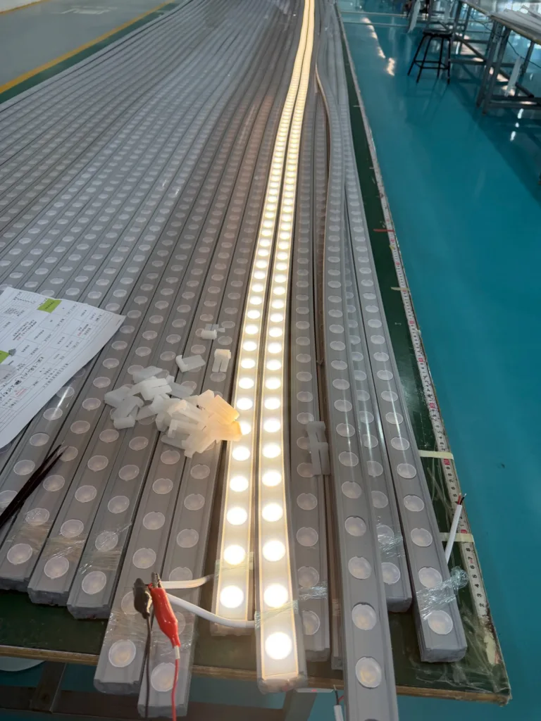
Most people only realize this when their project fails: the success of a Neon Flex Lights installation isn't determined by LED quality, brightness, or IP ratings. What truly matters is whether the entire material system, structural design, and installation approach can work together reliably over years of real-world environmental stress.
Here's what really causes projects to fail: In the lab, silicone, PCB, adhesives, end caps, power supplies, and aluminum channels all perform perfectly. But outdoors, when temperature cycles, UV exposure, moisture, wind loads, and structural stress combine, these materials begin interacting through thermal expansion, hardness shifts, adhesive degradation, and mechanical fatigue. Most failures aren't from one part breaking—they're from the entire system gradually losing balance under long-term stress.

I've witnessed this pattern repeat across dozens of projects. Let me share what actually happens when Neon Flex systems fail—and more importantly, how to prevent it.
Why Do Neon Flex Lights Fail When IP67 Tests Pass?
I remember one commercial building project that haunts me. Side-emitting Neon Flex passed every lab test. Installation looked flawless. Then summer arrived.
The facade surface temperature exceeded 70°C daily. The lights expanded during daytime heat, contracted at night. Because the installation system locked the strips rigidly with zero expansion allowance, the PCB endured constant tensile stress. Three months later, dark spots appeared at corners. Six months in, solder joints began cracking from fatigue. When the rainy season hit, those cracks became moisture entry points. Batch failure followed.
The critical issue wasn't waterproofing—it was thermal expansion stress management failure. When materials with different expansion coefficients are rigidly constrained without relief mechanisms, mechanical stress accumulates at connection points and corners until structural failure occurs, typically manifesting as PCB trace cracks or solder joint separation.
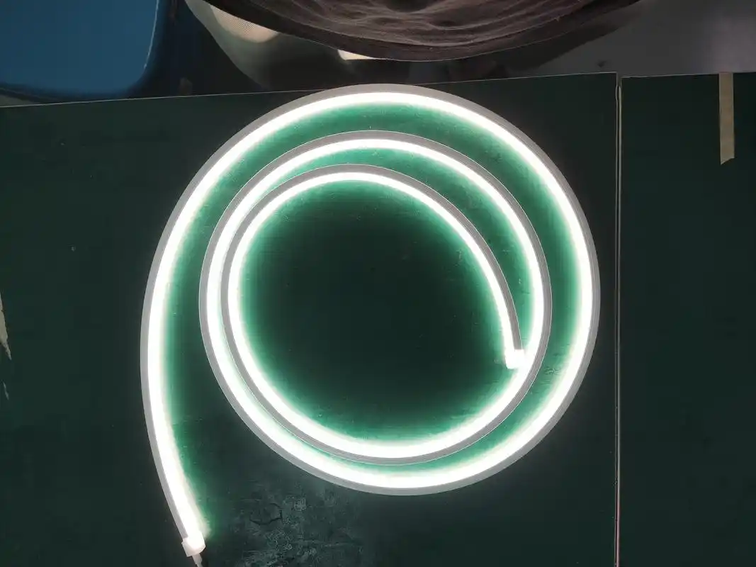
This pattern appears constantly in large-scale architecture, bridge landscapes, and chain brand facades. Yet most procurement teams still focus only on brightness and IP ratings.
The material compatibility challenge runs deeper than most realize. Each component—silicone body, PCB substrate, adhesive layers, end caps, wire insulation—has its own thermal expansion coefficient. When outdoor temperatures cycle from -20°C at night to 70°C on sun-exposed surfaces, these materials expand and contract at different rates.
If the installation method doesn't accommodate this movement, stress concentrates at the weakest points. That's usually corners, solder joints, or material interfaces. The failure happens gradually. First, microscopic cracks form. Then they propagate over months. Finally, moisture finds its way in through pathways that didn't exist during factory IP testing.
I've seen projects where every component passed individual testing, but the system failed because no one validated the complete assembly under realistic thermal cycling conditions.
What Causes Neon Flex Lights to Turn Yellow After One Year?
Here's the scenario I see repeatedly: samples arrive with perfect transparency and uniform light emission. First three months after installation look excellent. One year later, sun-facing sections start yellowing. Two years in, the building's south facade shows obvious color difference from the north side.
Most buyers think "anti-UV silicone" solves everything. They're missing the bigger picture. Yellowing rarely comes from the silicone base material alone.
Yellowing typically originates from diffusion powder migration, insufficient UV stabilizers, adhesive outgassing contaminating surface layers, mismatched material aging rates between components, or high-energy UV radiation breaking molecular chains. The problem isn't whether the silicone yellows—it's whether the entire material system maintains optical stability over time.

For genuine outdoor projects lasting five-plus years, asking "does it resist yellowing?" means nothing. What matters:
| Critical Factor | Why It Matters | What to Verify |
|---|---|---|
| UV aging test duration | Lab hours translate to real years | Minimum 1000 hours QUV exposure |
| Silicone curing system | Platinum cure resists yellowing far better than peroxide | Platinum-catalyzed vulcanization |
| Accelerated aging data | Lab results vs. outdoor exposure correlation | QUV test vs. Florida/Arizona weathering |
| Light transmission curve | Quantifies optical degradation | Transmission loss after aging |
| Color shift control | ΔE values show visible color change | ΔE < 3 after 3000 hours |
These metrics determine appearance after five years, not on delivery day. I learned this the hard way on a retail chain project where we replaced an entire installation at year two because the yellowing became brand-damaging.
The chemistry gets complex here. Even premium silicone can yellow if paired with incompatible diffusion agents or if the UV stabilizer package isn't sufficient for the installation latitude and orientation. I've tested samples where the silicone body remained clear, but yellowing occurred from plasticizer migration from adjacent PVC wire insulation.
This is why mature manufacturers run outdoor exposure testing in multiple climates, not just accelerated lab tests. Real sunlight contains UV wavelengths that lab equipment can't fully replicate. Temperature and humidity cycling in actual weather conditions reveals problems that static testing misses.
Where Does Water Actually Enter IP67-Rated Neon Flex Lights?
Most water ingress doesn't come from the silicone surface. It starts at the ends. Projects focus on the extruded silicone body while ignoring end caps, sealant systems, wire exit points, and the interface between cable and silicone.
In failure analysis, over 80% of water entry cases begin at these locations, not through the main body.
End-point sealing fails because while silicone handles long-term thermal expansion, the adhesive, end cap material, and cable jacket cannot match that flexibility. When thermal expansion coefficients mismatch, microscopic cracks gradually form at sealed interfaces. Static immersion testing doesn't reveal this—only annual hot-cold cycling exposes the problem.
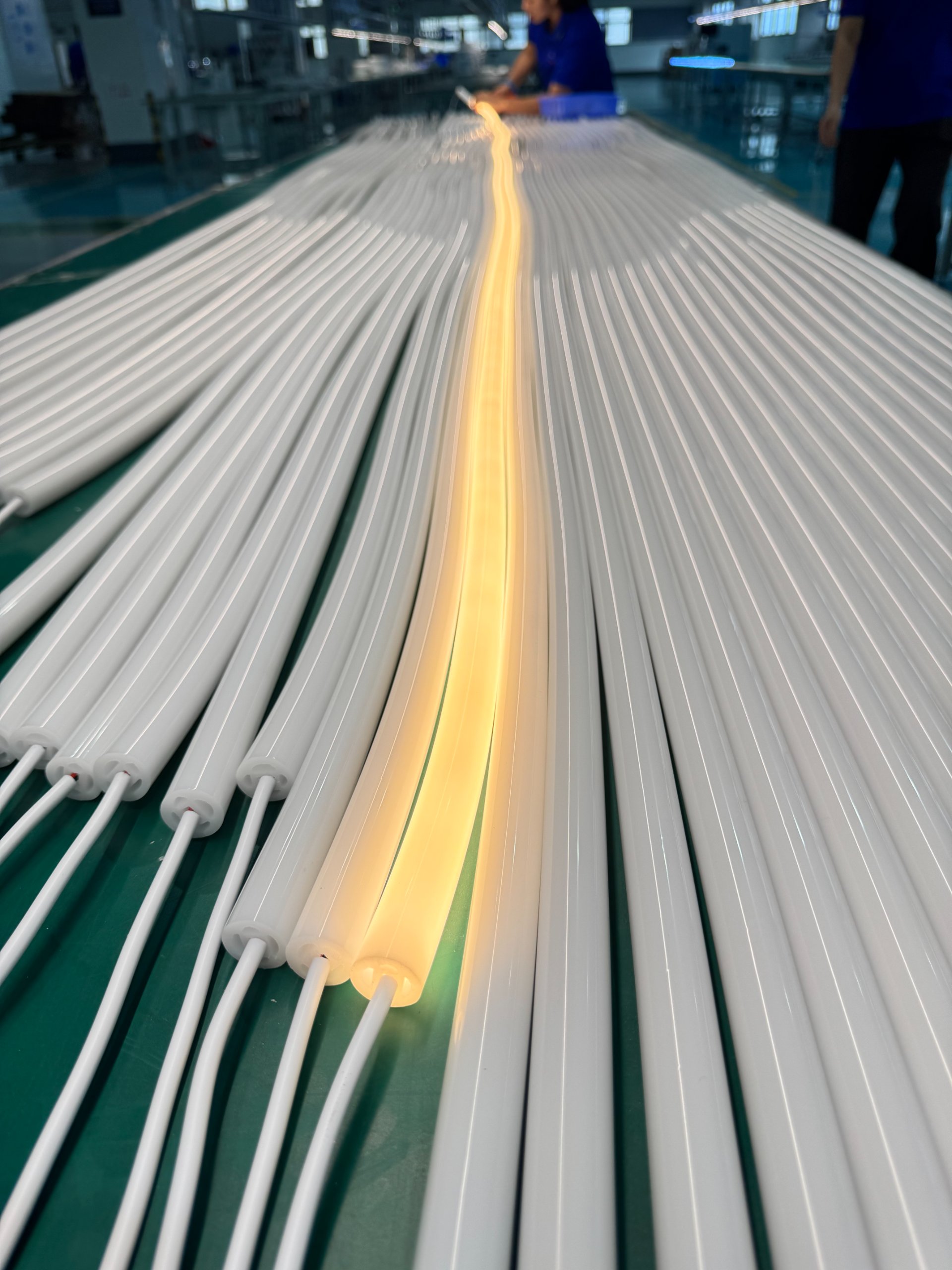
I've reviewed dozens of failed installations. The pattern repeats: perfect factory testing, excellent initial installation, then six to twelve months later, moisture appears inside the silicone tube near connection points or corners.
Why doesn't lab testing catch this? Because standard IP testing involves static immersion at room temperature for limited duration. Real installations face:
- Daily temperature swings of 40°C or more
- Thousands of expansion-contraction cycles annually
- Seasonal freeze-thaw in colder climates
- UV exposure degrading sealant elasticity
- Mechanical stress from wind loads and vibration
High-reliability projects don't just run IP67 testing. They validate through:
| Test Type | Purpose | Duration |
|---|---|---|
| Thermal shock cycling | -40°C to +90°C transitions | 500+ cycles minimum |
| Humidity-heat cycling | Combined moisture and temperature stress | 1000+ hours |
| Salt spray exposure | Coastal environment simulation | 500+ hours |
| UV + humidity combination | Realistic weathering conditions | 2000+ hours |
| Long-term mechanical tension | Simulates installation stress | 3000+ hours under load |
These tests reveal weaknesses that static immersion testing never will. I always recommend clients request thermal cycling test reports, not just IP certification documents.
How Should Large-Scale Neon Flex Light Projects Control Risk?
From an engineering risk perspective, "how bright is this Neon Flex?" is the wrong question. What actually matters for project success:
First—material system compatibility. Silicone, end caps, sealants, and cable jackets must undergo long-term compatibility validation together, not separately. Any single material aging at a different rate becomes a future failure point that compounds over time.
We source all sealing materials from verified suppliers who've tested compatibility with our specific silicone formulation. I've seen projects fail because someone substituted a "similar" adhesive to save costs, not realizing the original was specifically selected for thermal expansion matching.
Second—structural stress relief design. Large architecture projects must accommodate thermal expansion. Fully rigid mounting systems often mark the beginning of batch failures down the line.
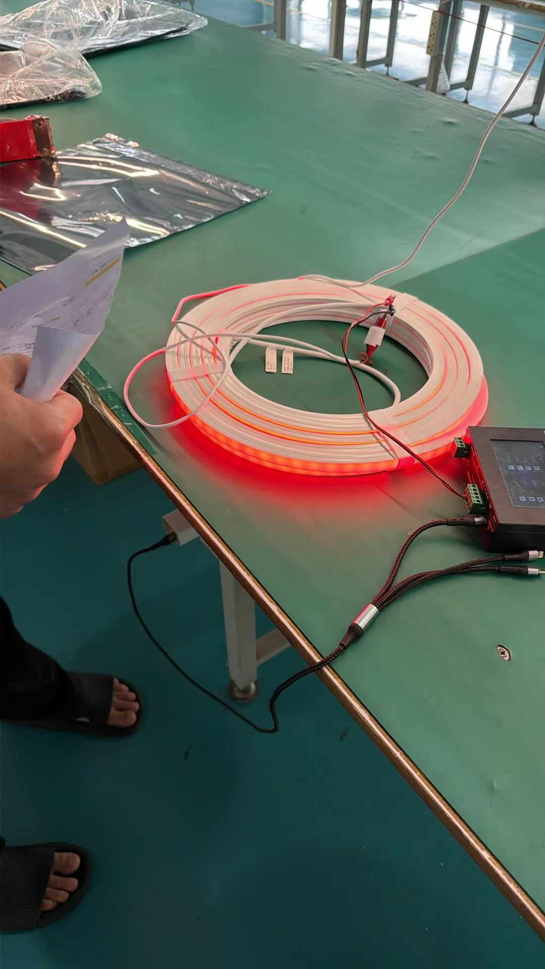
I design mounting systems with expansion loops every 10-15 meters for long runs. Corners get flexible mounting brackets that allow slight movement. High-stress points use larger radius bends to distribute flexing across more PCB length. These details seem minor during installation but prevent mechanical fatigue failures later.
Third—PCB design for long-term fatigue resistance. Critical areas require special attention: small-radius bends, corner installations, and locations experiencing frequent temperature cycling. These positions must minimize copper trace stress concentration. Otherwise the first failure isn't LED burnout—it's conductor structure breakdown.
Double-sided flexible PCBs with staggered vias help. Thicker copper layers (2oz vs. 1oz) improve fatigue life. Rounded corner traces reduce stress concentration compared to 90-degree angles. These manufacturing details cost slightly more but extend operational life dramatically.
Fourth—color temperature batch management. Building facade projects' biggest fear isn't single strip failure—it's color temperature drift between different production batches creating visible bands across the building at night. Maintenance costs far exceed fixture replacement.
| Color Management Practice | Implementation | Benefit |
|---|---|---|
| LED binning lock | MacAdam 3-step or tighter | Ensures visual consistency |
| Batch traceability | Serial number tracking | Enables matched replacements |
| Project-specific production runs | Dedicated manufacturing batch | Eliminates inter-batch variation |
| Pre-installation testing | Sample verification before install | Catches color issues early |
Mature projects don't simply order by nominal CCT specification. They require LED bin codes, validate samples from actual production batches, and maintain reserve inventory from the same manufacturing run for future repairs.
Fifth—don't confuse IP rating with lifespan. IP67 only confirms passing a test at one point in time. It says nothing about maintaining that seal capability after five years of environmental exposure.
What actually determines lifespan: material weather resistance, structural design quality, stress management effectiveness, and process consistency. I've tested supposedly IP68-rated products that failed after 18 months outdoors, and IP65-rated installations still performing after seven years. The rating is just the starting point.
Conclusion
Anyone who's managed large-scale Neon Flex projects knows: the biggest costs never come from initial procurement—they come from high-altitude repairs, business closure during maintenance, structural disassembly, brand image damage, and batch replacement claims. When you evaluate Neon Flex through material compatibility, thermal stress management, long-term aging mechanisms, and failure pathways, you're no longer just buying a light strip—you're controlling a project's five to ten-year risk curve. That's where real engineering value lives.